
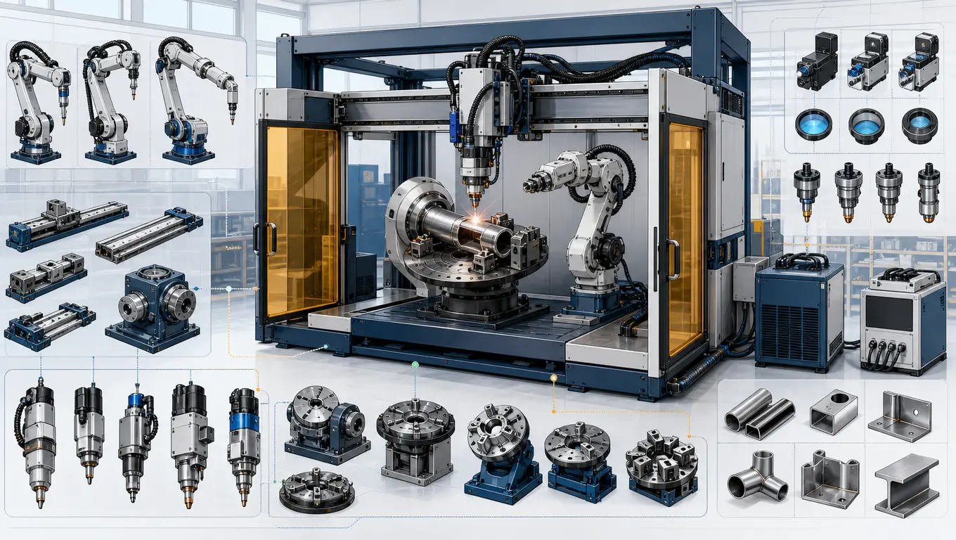
Estaciones de soldadura láser CNC multi-eje: guía de selección técnica
La fabricación de dispositivos médicos de alta precisión, componentes aeroespaciales y cajas electrónicas requiere uniones repetibles, estrechas y estructuralmente sólidas. La soldadura manual tradicional tiene dificultades para cumplir estas especificaciones estrictas, lo que impulsa la adopción de estaciones de trabajo de soldadura láser CNC multi-axial. Para implementar una estación de trabajo automatizada, los ingenieros deben evaluar cuidadosamente las disposiciones de ejes, la mecánica de los servoguidos y las vías ópticas. Esta guía proporciona un tutorial paso a paso para configurar un CNC máquina de soldadura láser de 3/4/5 ejes, ayudándole a ajustar las especificaciones del sistema a sus requisitos de producción.
Preparación y evaluación del espacio de trabajo
Antes de seleccionar el hardware, defina los requisitos físicos y mecánicos de sus componentes. Las configuraciones de ejes incorrectas pueden provocar errores de seguimiento dinámico, penetración insuficiente en la soldadura o colisiones mecánicas.
Lista de verificación técnica previa a la configuración
- Mapeo de la geometría de la pieza: Defina la trayectoria de la costura de soldadura. Las costuras planas, lineales o circulares en un solo plano requieren menos complejidad de ejes que los contornos curvos en el espacio 3D.
- Espacio para Herramientas y Sujeción: Considere el tamaño físico de las pinzas neumáticas. El volumen de trabajo debe acomodar tanto las piezas como sus accesorios de sujeción personalizados de alta precisión sin restringir el espacio libre óptico.
- Requisitos de Precisión Dinámica: Determine la tolerancia de trayectoria permitida. Las mesas accionadas por motores lineales ofrecen mayor precisión (inferior a ±5 micras) que los tornillos de bola estándar, lo que las hace ideales para aplicaciones de microsoldadura.
Selección y Configuración del Sistema Paso a Paso
Siga este proceso sistemático para configurar una estación de soldadura láser CNC adaptada a su aplicación:
Paso 1: Determine la disposición de los ejes (3 ejes vs. 4 ejes vs. 5 ejes)
El número de ejes interpolados determina la flexibilidad geométrica de la estación de trabajo:
- Configuración de 3 Ejes (X, Y, Z): Utiliza tres ejes lineales ortogonales. La cabeza láser se mueve verticalmente (Z) mientras que la pieza de trabajo o el pórtico se mueven en el plano horizontal (X, Y). Esta configuración es ideal para placas planas y perfiles 2D simples.
- Configuración de 4 Ejes (X, Y, Z + Eje R): Añade un eje rotativo. Al integrar sincronizados posicionadores rotativos de un solo eje, el sistema puede rotar piezas cilíndricas (como sensores, carcasas de motores o tubos) mientras la cabeza láser realiza un seguimiento lineal.
- Configuración de 5 Ejes (X, Y, Z + Ejes de Inclinación/Giro): Incorpora dos ejes de rotación (generalmente una mesa inclinable o un cabezal láser inclinable de 2 ejes). Esta configuración permite que el haz láser mantenga un ángulo perpendicular con respecto a superficies tridimensionales complejas y curvas.
Paso 2: Seleccione la fuente de láser de fibra y las ópticas de transmisión
Seleccione una fuente de láser de fibra con una potencia nominal adecuada al grosor del material (típicamente de 1 kW a 3 kW). Para aplicaciones de alta precisión como electrónica o dispositivos médicos, los láseres de fibra de modo único con un tamaño de punto pequeño (10-50 micras) proporcionan una penetración profunda con una entrada de calor mínima. Combine el láser con un cabezal de soldadura oscilante para ayudar a compensar las variaciones de ajuste sin comprometer la resistencia de la soldadura.
Paso 3: Elija el controlador CNC y el accionamiento de movimiento
El controlador de movimiento coordina los pulsos de activación del láser con las coordenadas de los ejes físicos. Para evitar perforar las esquinas, elija un controlador que soporte “modulación de frecuencia de potencia láser”, que ajusta automáticamente la potencia de salida del láser en relación con la velocidad instantánea de los ejes CNC.
Paso 4: Diseñe sistemas de sujeción y herramientas personalizados
Dado que la soldadura láser utiliza un haz altamente enfocado, mantener un ajuste estrecho entre piezas es crítico. Diseñe accesorios de sujeción personalizados de alta precisión utilizando placas de respaldo de cobre o aluminio. Estos materiales aseguran las piezas y actúan como disipadores de calor, extrayendo rápidamente el calor de la zona de soldadura para evitar deformaciones térmicas.
Paso 5: Encierre la estación y configure el gas de protección
Los láseres de fibra operan a una longitud de onda de 1064 nm, lo que puede causar daño ocular permanente. Encierre la estación de trabajo en un gabinete certificado Clase 1 seguro para láser con puertas de acceso con interbloqueo y ventanas de observación con clasificación para láser. Configure canales duales de gas de protección (coaxial para proteger el baño de soldadura y purga trasera para proteger la raíz) para prevenir la oxidación.
Matriz de configuración de la estación de trabajo
Esta matriz de comparación resalta las capacidades, aplicaciones objetivo y niveles de inversión de varias configuraciones de estaciones de trabajo CNC:
| Tipo de estación de trabajo | Detalles del sistema de movimiento | Pieza objetivo típica | Precisión de trayectoria | Nivel de inversión |
|---|---|---|---|---|
| CNC de pórtico de 3 ejes | Etapas de tornillo de bolas lineales (X, Y, Z) | Chapa plana, gabinetes electrónicos lineales, barras colectivas de paquetes de baterías. | ±0,02 mm | Nivel inicial a medio |
| CNC rotativo de 4 ejes | Lineal X,Y,Z + Accionamiento directo Posicionador rotativo | Sensores, baterías cilíndricas, catéteres médicos, tuberías circulares. | ±0,01 mm | Nivel medio |
| CNC de pórtico de 5 ejes | Lineal X, Y, Z + Mesa inclinable/rotativa de 2 ejes | Tubos conformados hidrolíticamente, carcasas aeroespaciales complejas, componentes automotrices. | ±0,015 mm | Nivel alto |
| Lineal de doble accionamiento de 5 ejes | Motores lineales de accionamiento directo + Cabeza galvo de alta velocidad | Microsoldadura láser de alta velocidad, marcos semiconductores, implantes médicos. | ±0,005 mm | Premium → 1. Premium |
Precisión dinámica y calibración de trayectoria
Para mantener la precisión de la trayectoria en configuraciones multieje, implemente procedimientos de calibración estándar durante la configuración:
- Alineación del eje rotativo: Utilice un indicador de carátula o un interferómetro láser para alinear la línea central del mandril rotativo con los ejes de desplazamiento lineal, minimizando el juego radial durante la rotación.
- Calibración dinámica del punto central de la herramienta (TCP): En sistemas de 5 ejes, calibre los centros de pivote rotacional para asegurar que el punto focal del láser permanezca fijo en la costura durante los movimientos de inclinación y rotación.
- Escalas lineales de bucle cerrado: Para aplicaciones de alta precisión, instale escalas lineales ópticas para proporcionar retroalimentación directa de posición al controlador CNC, compensando cualquier expansión térmica o juego mecánico.
Máquina de soldadura multi-axial: Configuraciones y cuándo vale la pena cada una
Una máquina de soldadura multi-axial es cualquier sistema que mueve la pieza, la antorcha, o ambos, a lo largo de más de un eje controlado. La configuración determina el acceso a la unión, y el acceso a la unión determina si el proceso es repetible o no.
| Configuración | Ejes | Uso típico |
|---|---|---|
| Posicionador rotativo | 1–2 | Costuras circulares o longitudinales presentadas a una antorcha fija. |
| Mesa de inclinación y rotación | 2 | Mantener la soldadura en posición plana o horizontal para secciones más pesadas. |
| Puente con 3–5 ejes | 3–5 | Piezas grandes o largas que es más fácil mover debajo de la cabeza que rotar. |
| Robot de 6 ejes | 6 | Uniones 3D complejas y trabajo de múltiples pasadas en un solo soporte. |
| Robot más posicionador | 7–9 combinados | Movimiento coordinado, donde la mesa y el robot se mueven juntos. |
Soldadura por haz láser multi-axial: lo que realmente aportan los ejes extra
- Continuidad del recorrido — una costura soldada sin detenerse evita los defectos de inicio/parada que introduce una pieza re-apretada.
- Control del ángulo del haz respecto a la unión — en la soldadura láser, el ángulo de incidencia afecta el acoplamiento y la estabilidad del keyhole, por lo que presentar la unión de manera consistente es más importante que el número bruto de ejes.
- Acceso a uniones ocultas — los ejes que reposicionan la pieza pueden reemplazar un segundo soporte y una segunda operación.
Lista de verificación para la selección
| Decidir | Porque |
|---|---|
| ¿Se mueve la pieza, se mueve la antorcha, o ambos coordinados? | Define la clase de máquina y la arquitectura de control. |
| Precisión posicional requerida en la unión | El error de eje acumulado se manifiesta directamente como desalineación de la costura. |
| Si el movimiento coordinado es realmente necesario | Es el mayor paso de costo y puesta en marcha. |
| Intervalo de calibración y recalibración | La precisión multi-axial se desvía; el plan para restaurarla debe existir antes de la compra. |
Preguntas frecuentes
P: ¿Cuáles son las principales diferencias entre una máquina de soldadura láser de 3 ejes y un brazo robótico de soldadura?
R: Un pórtico CNC de 3 ejes utiliza etapas lineales rígidas, que generalmente ofrecen mayor rigidez mecánica y precisión de trayectoria (±0,01 mm) en envolventes pequeños a medianos. Los brazos robóticos articulados proporcionan mayor flexibilidad geométrica y un alcance más amplio, pero generalmente operan con una tolerancia de trayectoria ligeramente más amplia (±0,05 mm a ±0,1 mm).
P: ¿Puede una soldadora láser automática funcionar tanto en modo de pulso como en modo continuo?
R: Sí, los láseres de fibra modernos pueden operar tanto en modo de onda continua (CW) como en modos pulsados de onda continua cuasi-continua (QCW). Los modos pulsados QCW son altamente efectivos para componentes electrónicos sensibles al calor, ya que permiten que el material se enfríe entre pulsos, reduciendo la zona afectada por el calor.
P: ¿Por qué es crítica la selección del gas de protección para aleaciones de titanio y aluminio?
R: El titanio y el aluminio son altamente reactivos a temperaturas elevadas. La exposición al oxígeno o nitrógeno durante la soldadura puede causar fragilización y porosidad. Es esencial utilizar gas de protección de argón de alta pureza (99,99%) o helio para aislar la piscina de soldadura de los gases atmosféricos.
Conclusión y diseño de estación de trabajo personalizada
Configurar una estación de trabajo de soldadura láser CNC requiere equilibrar velocidades de recorrido, flexibilidad de coordenadas y precisión mecánica. Combinar la disposición de ejes adecuada con un láser de fibra de alto rendimiento y soportes de sujeción seguros es clave para lograr soldaduras consistentes y de alta calidad. TrueSyn diseña y construye estaciones de trabajo de soldadura láser CNC llave en mano adaptadas a las tolerancias y tiempos de ciclo de su aplicación. Contacte a nuestro equipo técnico hoy para discutir su proyecto, realizar soldaduras de prueba en sus piezas o configurar un sistema personalizado.
Consulte con los Ingenieros Técnicos de TrueSyn
Contáctenos para revisar los diseños de sus componentes y objetivos de automatización:
- Correo electrónico: wangd@zjcxlaser.com
- WhatsApp (Sr. Peng): +86-13615855016
- WhatsApp (Sra. Wang): +86-13185595609
- Vea nuestras estaciones de trabajo en YouTube: Canal de Automatización Láser TrueSyn
Soluciones de soldadura láser multi-eje: Adaptación de la celda a la soldadura
La cantidad de ejes es la parte más económica de las soluciones de soldadura láser multi-eje; la integración
alrededor de los ejes es lo que determina el éxito o el fracaso de la celda. Una solución fiable adapta tu horario de
soldadura a cuatro elementos: movimiento (ejes y posicionadores), seguimiento de soldadura, relleno y protección
por gas de protección, y sujeción; luego demuestra la combinación en tu pieza antes de firmar.
| Tipo de soldadura | Configuración típica | Pieza de integración crítica |
|---|---|---|
| Recta, de longitud completa | Portaplanos o 6 ejes, pieza fija | Sujeción que no obstruya la cabeza |
| Circunferencial | Robot + rotador de 1 eje | Concentricidad de la pieza en el rotador |
| Fuera de posición / 3D | Robot + posicionador de 2 ejes | Movimiento coordinado durante la soldadura |
| Uniones con variación de gap | Cualquiera de los anteriores + seguimiento de soldadura | Latencia del sensor vs. velocidad de desplazamiento |
Lista de verificación para soluciones de proveedores: una simulación de tiempo de ciclo en tu horario de,
soldadura, no una demostración en el de ellos; soldaduras de muestra en tu material y grosor; el archivo de
seguridad láser propiedad del integrador; y una transferencia de datos declarada (códigos de falla, energía por soldadura) si la
celda debe reportar hacia arriba. Las soluciones que omiten estos cuatro están vendiendo ejes, no soldaduras.
Índice de guía: lectura relacionada
- Servicios de soldadura láser — la página de servicios detrás de cada configuración en esta guía
- Robot de soldadura MIG/MAG — un robot listo para producción para combinar con una estación de trabajo multieje
- Sistemas de soldadura con cobots: Cuando los robots colaborativos ganan — la alternativa de menor capacidad de carga a una estación de trabajo pórtico
- Robots de soldadura láser en la fabricación de baterías para vehículos eléctricos — una aplicación de gran volumen donde la interpolación de 5 ejes paga sus frutos
Bancos de trabajo que construimos: el robot de soldadura láser de la serie FANUC para celdas automatizadas de alto volumen, el Posicionador de 3 ejes para trabajos de múltiples caras, y el soldador portátil de refrigeración por agua para posiciones manuales a las que la celda no puede llegar.