
Зона захвата робота и подача деталей: исследование, которое покупатели должны рассматривать
Every robot datasheet quotes a reach figure in millimetres, and almost every buyer reads it as a capability. It is a geometric ceiling, measured to a point on the wrist at a specific payload, with no torch, no cable package and no part in the way. Whether an assembly can be welded depends on how that envelope interacts with how the part is presented – which is what a reach and part presentation study establishes.
The study asks one question: for every weld, in every orientation the fixture will hold it, can the robot reach the seam at a workable torch angle, without collision or an axis limit, inside the cycle budget? Answering it before contract costs days of engineering; afterwards it costs fixture redesign and rework.
Why Published Reach Is Not a Working Envelope
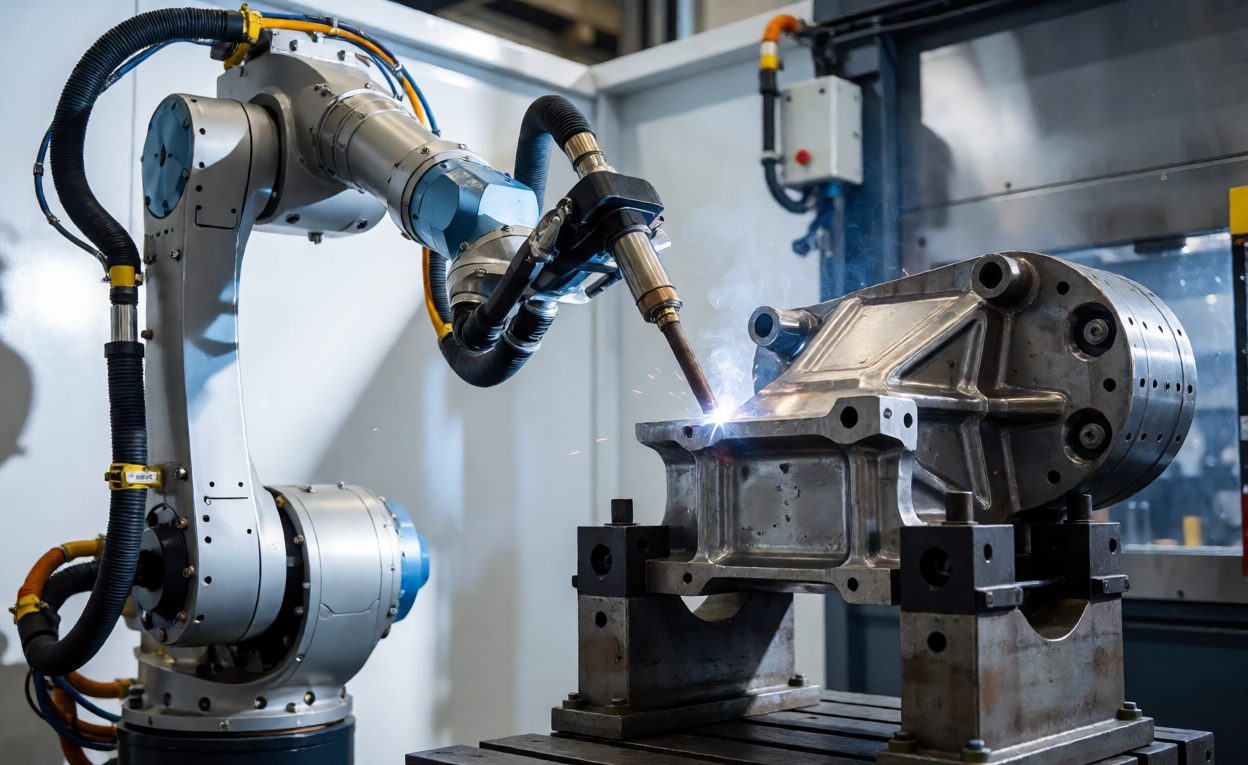
The figure in the brochure is measured with the arm fully extended and is usually quoted at a light payload. Four corrections have to be applied before it means anything on a real cell:
- Payload derating: the welding head, cable package, feeder mount and sensor bracket all consume payload, and the envelope shrinks mostly at the far boundary where optimistic layouts place work.
- Wrist and axis travel limits: an arm can sit inside its reach sphere and still be unable to point the torch as required, because a wrist axis has reached its travel limit.
- Torch offset: the wire tip sits 150 to 350 mm from the wrist flange, and the head has a body with a nozzle and gas shroud. A head that clears a clamp on approach may not clear it on exit.
- Dressing and routing: a dressed arm is wider than a bare one, and hose packages catch on fixture edges at the reach extremes.
- Mounting arrangement: floor, wall or inverted mounting relocates the envelope; a rail converts a sphere into a prism, often the cheapest fix for a shortfall.
Reach should therefore be discussed as a working volume around a fixture rather than as a radius. The роботизированную сварочную ячейку article covers the equipment decisions that produce that volume; the study demonstrates it is big enough, and the multi-axis workstation selection guide sets out the configurations available when it is not.
Part Presentation: The Other Half of the Problem
A reach problem is often a presentation problem in disguise: the assembly that is unreachable lying flat may be comfortable tilted at thirty degrees, because tilt brings the seam into a region where the wrist has freedom. Presentation is a design variable, decided mostly by the fixture and positioner rather than by the robot:
- Clamp placement: clamps must hold the part and leave the seam accessible; clamps drawn for holding strength alone routinely sit where the torch needs to pass.
- Tilt strategy: welding in the flat position is more forgiving on penetration, and a positioner that brings each seam to a favourable orientation is often worth more than a larger robot.
- Fixture height: raising the part moves it into a region of better wrist freedom.
- Load clearance: a fixture that presents well but needs a forklift to load has moved the problem.
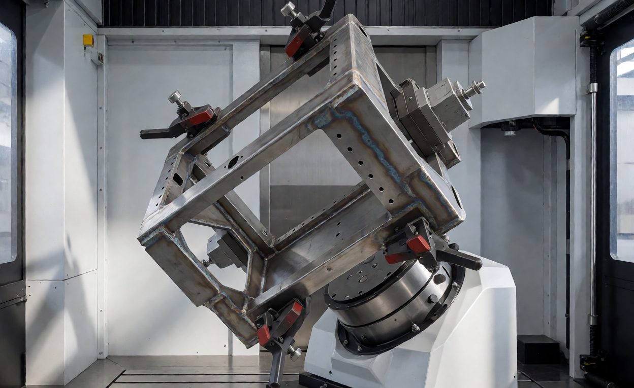
Fixture design carries most of this. The fixture design guide sets out how clamping, datum strategy and positioner choice combine; the study tests them against the actual robot. Where variants are frequent, the quick-change and pallet systems article covers swapping between them. Inverse kinematics decides whether a requested torch pose has a solution at all, and singular postures are what simulation exposes before anything is built.
How to Run the Study Before Contract
A useful study is not elaborate. It needs four inputs, and a competent supplier should produce it at quotation stage:
- Part geometry: the customer’s own CAD at the real tolerance range, not an idealised model.
- Weld list: every seam with length, position, required torch angle and access restrictions.
- Fixture concept: clamp positions, height and positioner arrangement, even as a sketch.
- Конфигурация робота: model, mounting, rail travel and the head and dressing to be used.
The output is worth insisting on in writing: a reach map showing every seam reachable at an acceptable torch angle, plus a list of failures with the reason. Remedies are then a different tilt, a rail, or a scope decision to weld that seam another way. Checking early also pays back in cycle time work after commissioning, since programmes written inside a comfortable envelope run faster.
Where Reach Studies Go Wrong
Four failure patterns account for most cases where a study passed but the cell still struggled:
- Ideal geometry: parts arrive with real fabrication variation, and the answer changes once the tolerance range is modelled.
- No collision checking: reach alone ignores the torch body, cable package and fixture; a seam can be reachable yet not approachable.
- Single-orientation answers: a seam reachable at one tilt may fail once the positioner rotates for the next.
- Maintenance access: if head removal, nozzle and window positions are not inside a comfortable volume, service becomes a two-person job.
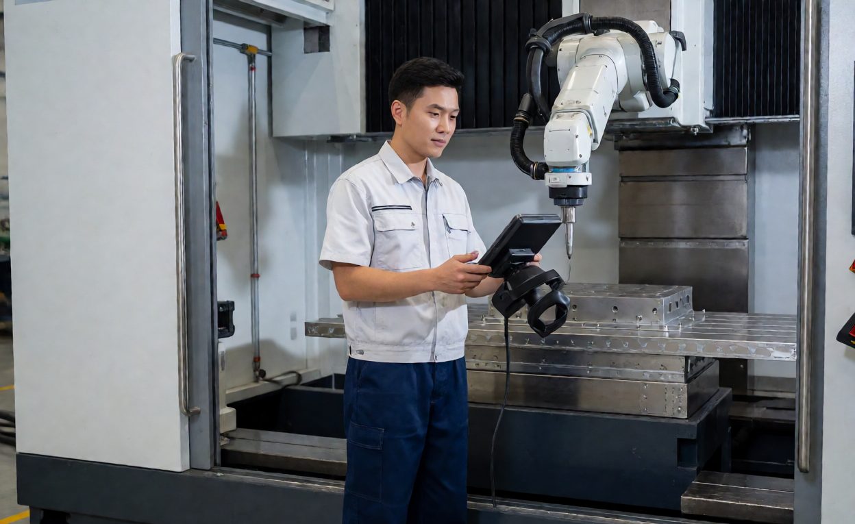
The floor check closes the loop: a dry run with the laser off, watched by the buyer’s welding engineer and the supplier’s programmer, catches what simulation misses, and is the point to agree who owns any resulting fixture change – the tooling scope and ownership question. Degrees of freedom describes what the arm can do at a given pose, and jig and fixture practice explains why tooling is designed alongside the process. Machines chosen on a робот для лазерной сварки reach comparison alone are usually oversized.
Часто задаваемые вопросы
Is the published reach figure the working envelope?
No. It is measured at a wrist point with a light payload and no tooling. Payload, wrist limits, torch offset and dressing all reduce it.
Can a reach problem be solved without a bigger robot?
Often yes, by tilting the part, changing clamp positions, or adding a linear rail. Presentation fixes are usually cheaper than a larger arm.
What should the study output contain?
A reach map showing every seam reachable at an acceptable torch angle, plus an explicit list of any seam that fails and the reason.
How accurate does the part model need to be?
Close to production reality, including tolerance variation. Studies run on idealised CAD give optimistic answers.
Does collision checking matter as well as reach?
Yes. A seam can be reachable but not approachable once the torch body, cable package and fixture are considered.
Should the study cover maintenance positions?
Yes. Nozzle changes, window cleaning and head removal should all sit inside a comfortable working volume.
When should the study happen?
During quotation, before contract. A dry cycle check on the floor after delivery confirms what the simulation predicted.