
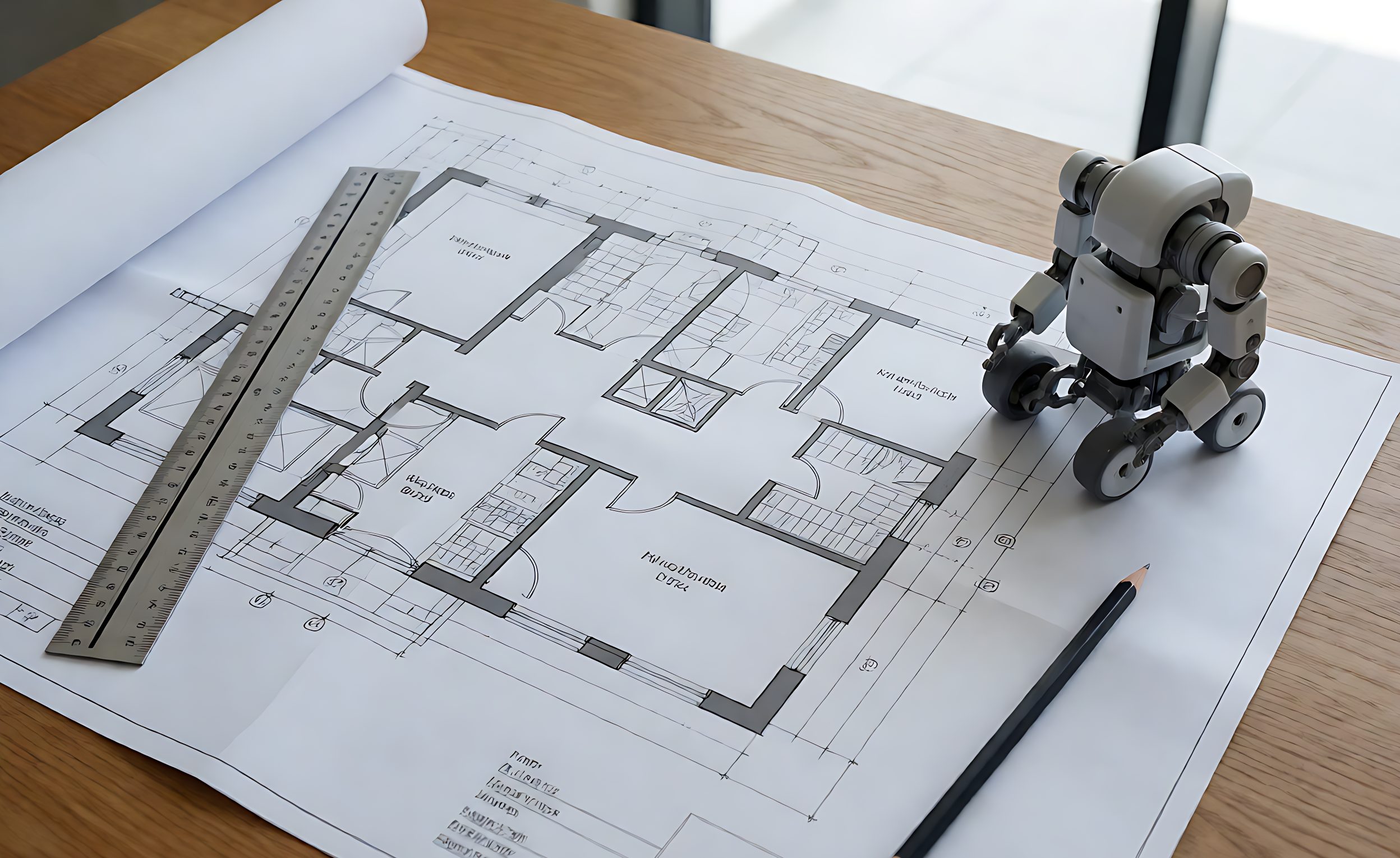
レーザー溶接セルのフットプリントとレイアウト計画:バイヤー向けのガイド
Manufacturers publish a footprint figure for every welding cell, and it is accurate, complete and almost useless on its own. The number describes the machine. What a buyer needs to plan is the installation: everything the cell touches, everything that travels to and from it, and everyone who has to reach it. Cells that fit on paper and fail in practice almost always fail for one of those reasons.
Planning the footprint has an order. Start from the machine envelope, add the surrounding zones one at a time, and only then decide the arrangement. Doing it in reverse – squeezing a fixed arrangement into an available corner – is how cells end up with no room to service them.
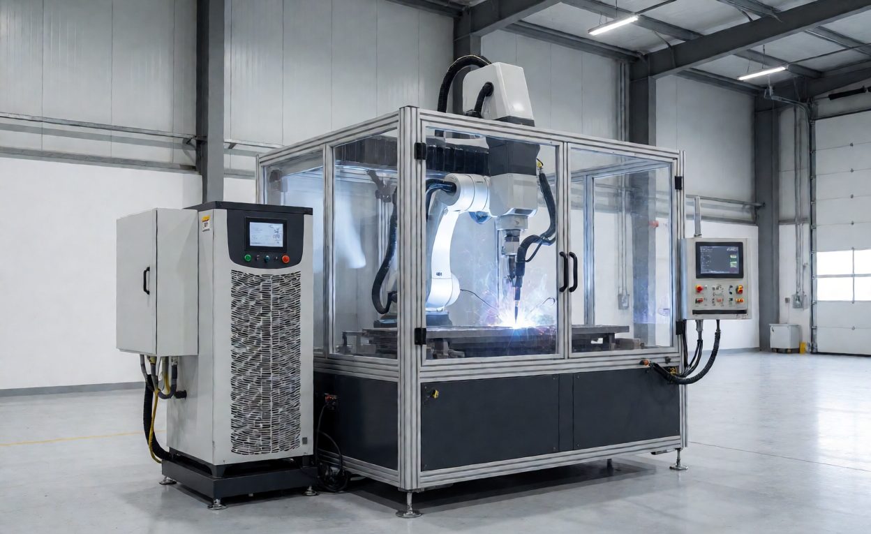
What the Machine Envelope Actually Includes
Ask for a layout drawing that shows each component as a separate item, not a single overall rectangle. The items that matter individually:
- Enclosure and doors: the safety enclosure sets the core rectangle, and door swing or slide adds its own swept zone. Rear access panels matter too – they need to open without moving anything parked behind the cell.
- Chiller and laser source: usually beside or behind the enclosure, each with front access for filters, coolant checks and module replacement.
- Control cabinet: needs door swing and standing room for an engineer with a laptop.
- Extraction unit and ducting: the filter unit has a footprint of its own, and ducting routes overhead or along the floor at the cost of turning space.
- Positioner swing: a rotary or trunnion positioner moves through a swept volume that must stay clear, including during loading.
- Robot reach envelope: mostly inside the enclosure, but worth confirming against the fixture envelope, because a reach conflict discovered at commissioning is expensive.
The surroundings then add three more layers. Operator access, maintenance access, and the safety perimeter described in Class 4レーザー安全記事に all extend the effective footprint well beyond the enclosure walls, and all three are easier to argue about on a drawing than on a finished floor.
Operator Position and Material Flow
The operator position shapes the layout more than any other single choice. Three patterns cover most installations:
- Front load station: a roller table or pallet staging area in front of the cell creates a linear flow from raw parts to finished weldments. Simple to understand, and it roughly doubles the installation depth.
- Two-station positioner: load one station while the other welds. Compact and productive, but the swing zone and the operator position must not conflict.
- Conveyor-fed: suits higher-volume single-part work, but the conveyor approach and exit routes fix the orientation of the cell within the building.
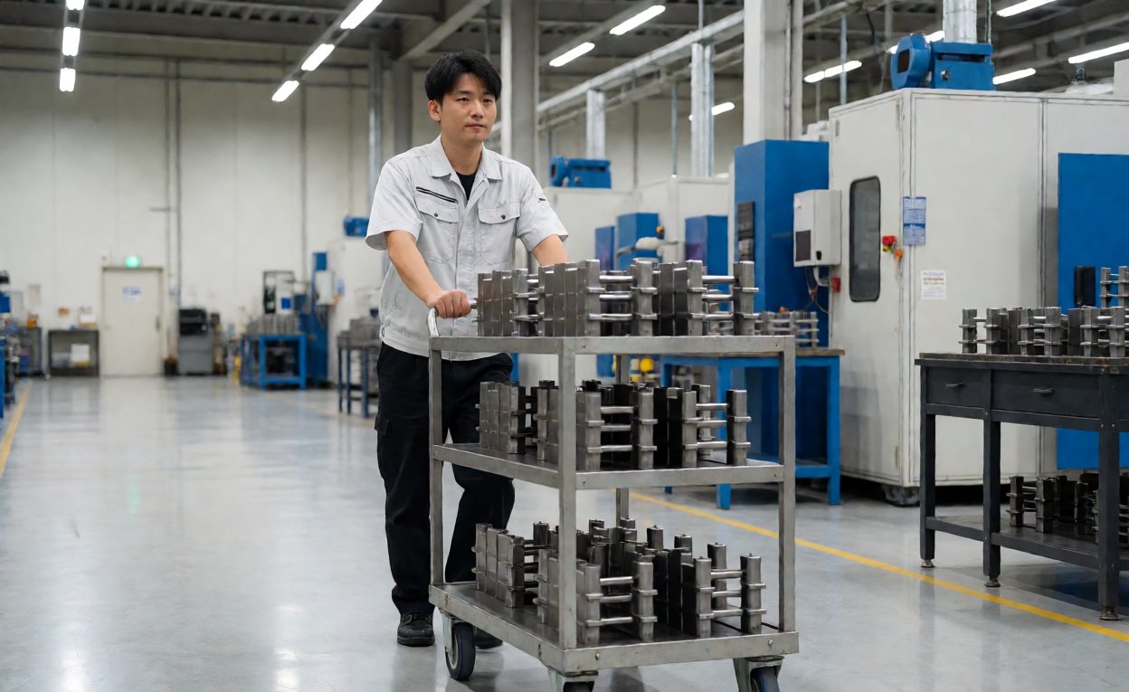
Flow thinking matters even at low volume. Parts arrive, fixtures travel to and from the cell, and weldments leave for inspection or finishing. A layout that forces those movements to cross each other, or to pass through a walkway, will generate exactly the congestion a layout plan exists to prevent. The ロボット溶接セル article covers the equipment set in general terms; the layout question is about how that equipment sits in a specific building with specific traffic.
Clearances That Plans Routinely Forget
- Servicing depth: laser modules and chiller components sometimes withdraw from their housings; the withdrawal distance must be free floor, not another machine.
- Door heights and overhead routes: extraction ducting, cable trays and any rail system all live above the cell, and low doorways constrain both ducting routes and machine access.
- Installation access: the cell is crated, delivered and assembled in place. Crates, a lifting route and temporary staging all consume floor during installation week, which is why the installation requirements article lists site readiness as a checklist rather than a suggestion.
- Foundation work: if the slab needs attention before the cell can be anchored, that work needs access too; the foundation and anchor bolt specification article explains what the floor must provide.
- Future expansion: a second cell, a longer conveyor or an added positioner. Leaving an unused bay beside the first cell is the cheapest expansion capacity available.
Utilities belong in the footprint plan as well. Power drops, water piping, compressed air and extraction takeoffs enter the cell at specific points, and the power and chiller sizing article sets out what the site must deliver. Routing those services is a floor-space decision in itself.
Layout Patterns and the Discipline Around Them
Most installations fall into one of three arrangements: the cell against a wall with flow along it, the cell as an island with flow around it, or paired cells sharing one operator and one staging area. Each is legitimate; the mistake is choosing by habit rather than by flow. Plant layout study is the established discipline here, and even a lightweight version of it – a sketch of part movements – separates an adequate layout from an obstructed one.
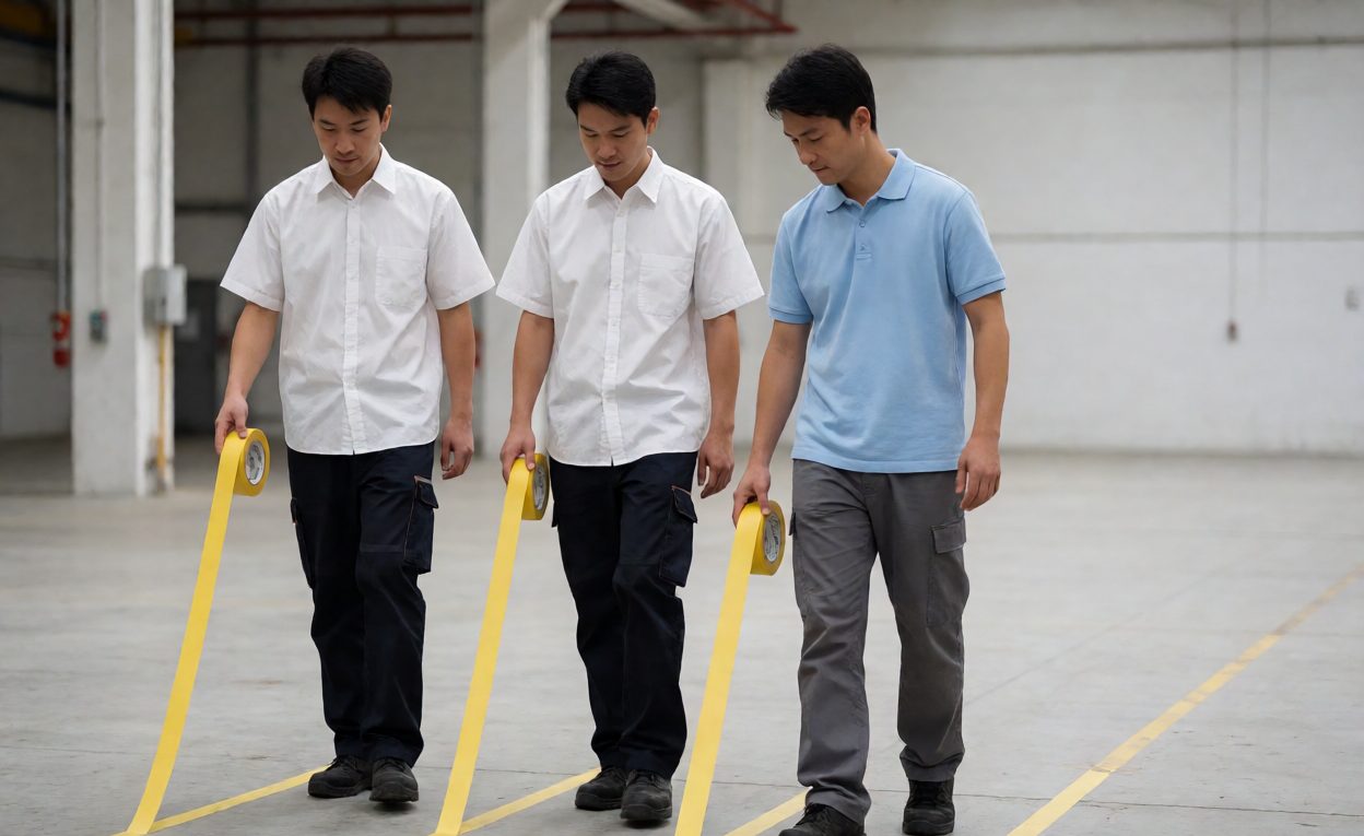
The same discipline applies to what surrounds the cell. Staging racks, wire storage, fixture cabinets and waste bins all need locations, and material handling practice offers a simple rule: nothing staged where it blocks a service door, and nothing stored where it narrows an escape route. Where several cells share a floor, a quick value stream map of the whole line usually reveals that the welding cell is not the bottleneck – and that the space around it, rather than the cell itself, was constraining output.
よくある質問
溶接セルには、データシート上のフットプリントを超える空間がどれだけ必要ですか?
Commonly thirty to fifty percent more once access doors, servicing zones, staging and flow routes are added. Ask for a layout drawing with each component itemised.
2工程ポジションnerは前積工程より良いですか?
For throughput, usually yes, because loading overlaps welding. It needs a swing zone and a clear operator position, so it is not automatically the smaller option.
Can the chiller be placed away from the cell?
Distance costs cooling performance, floor space and pipework. Keep it close unless the plant room offers genuine advantages.
How much clearance do service doors need?
Enough for the door to open fully with nothing parked against it, plus standing room for the work to be done. Mark these zones on the floor plan.
Should staging be inside the cell footprint?
Usually not. Staging inside grows the floor plan by roughly a third; staging outside needs a planned flow route instead.
What overhead services affect layout?
Extraction ducting, cable trays, lighting and any rail system. Check door heights and available ceiling space early.
When should the layout be finalised?
Before contract. Layout changes after delivery are the most disruptive kind, because services, anchors and flow routes are already fixed.