
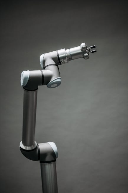
Industrial Robotic Bending Machines for Precision Metal Forming Automation
Robotic Bending Machines: Precision Metal Forming Automation
Optimizing Automotive Production with Robotic Bending Systems
Modern metal fabrication relies on robotic bending machines to achieve micrometer-level precision while reducing operational costs. These systems combine multi-axis kinematics with real-time sensor feedback, enabling complex bending operations at speeds exceeding 600 bends/hour in high-volume production environments. For example, a European automotive supplier implemented TrueSyn Bending Robot cells to produce electric vehicle battery enclosures, achieving 99.8% dimensional consistency across 12,000 parts/week while reducing rework by 75%. Key technological components enabling this performance include:
- High-torque servo motors with 0.01° angular resolution for precise motion control
- Adaptive algorithms compensating for material springback in real-time
- Modular end-effectors handling sheet metal blanks from 0.8-5.0mm thickness
Case Study: A Japanese OEM replaced three hydraulic press brakes with two robotic bending cells, reducing floor space requirements by 40% while maintaining ±0.08mm straightness across 2.5m structural components. The system’s AI-driven vision system automatically adjusts bending parameters based on material lot variations, eliminating manual quality checks between batches.
Technical Advantages Over Traditional Bending Methods
Bending Robots deliver measurable improvements over conventional press brakes:
- Micron-Level Accuracy: Closed-loop feedback systems maintain ±0.05mm tolerances through continuous laser interferometry monitoring of tool position and material deformation. For instance, in aerospace component manufacturing, this precision ensures perfect fit between bent brackets and composite panels, eliminating secondary machining operations.
- Flexible Production: Modular tooling systems handle 0.5-6mm material thicknesses and 15°-180° bending angles with 15-minute changeover times. TrueSyn’s QuickSwap™ tooling interface allows single operators to reconfigure cells for different part families without specialized equipment.
- Energy Efficiency: Servo-driven actuators consume 30-40% less power than hydraulic systems, achieving 0.8kWh per bend cycle. In a 24/7 production scenario, this translates to annual energy cost savings exceeding $120,000 per machine.
- Reduced Downtime: Automated laser alignment cuts setup time by 70% through machine vision-based material scanning. A German automotive parts manufacturer reported 18% increased OEE (Overall Equipment Effectiveness) after implementing this technology.
| Performance Metric | Robotic Bending Machine | Traditional Press Brake |
|---|---|---|
| Positioning Accuracy | ±0.05mm | ±0.2mm |
| Energy Consumption | 0.8kWh/cycle | 1.3kWh/cycle |
| Changeover Time | 15-25 minutes | 2-4 hours |
| Tool Wear Rate | 45% lower | Standard |
Technical Deep Dive: The energy efficiency gains stem from servo-electric drives eliminating constant pump operation required in hydraulic systems. Additionally, robotic systems’ reduced tool wear extends die replacement intervals from weekly to bi-monthly in typical stamping operations, as demonstrated in a 12-month study at a South Korean appliance manufacturing facility.
Automotive Industry Integration Challenges
Automotive manufacturing demands specialized capabilities:
- Material Handling: Process high-strength steels (up to 1,200 MPa) with adaptive force control adjusting to material batch variations. TrueSyn’s system maintains consistent bending force within ±1.5% tolerance even when material tensile strength fluctuates by ±8%.
- Complex Geometry: Execute multi-radius bends using 7-axis kinematics with ±0.2° angular precision. This capability proved critical for producing curved EV battery frames requiring three different bend radii within 0.5mm positional accuracy.
- System Integration: Digital twin coordination with upstream cutting and downstream welding systems. A case study at a U.S. automotive plant showed 22% reduction in inter-process alignment issues through synchronized digital modeling.
Implementation Challenges Addressed:
- Material springback compensation algorithms for AHSS (Advanced High-Strength Steel)
- Vibration damping systems maintaining accuracy during concurrent multi-axis motion
- Collision avoidance software for complex tooling arrangements
Advanced Sensor Integration for Process Control
Multi-sensor fusion architectures maintain process stability through:
- Torque feedback sensors (±2% accuracy) in strain-wave gearboxes: Monitor motor load to detect tool wear anomalies before they affect part quality
- 3D laser profilers compensating for material surface variations: Adjust Z-axis position within ±0.03mm to maintain bend consistency across textured surfaces
- Thermal imaging monitoring tool temperature drift: Maintains dimensional stability by compensating for tool expansion at elevated operating temperatures
Case Study: A Chinese EV manufacturer implemented thermal imaging sensors to address tool drift issues during extended shifts. The system automatically adjusts bending parameters when temperature deviations exceed 0.5°C, maintaining consistent part geometry across 16-hour production runs. Sensor Data Utilization:
| Sensor Type | Sampling Rate | Control Loop Response |
|---|---|---|
| Laser Profiler | 20kHz | Real-time |
| Torque Sensor | 10kHz | Preventive |
| Thermal Camera | 1Hz | Predictive |
Workflow Optimization Through Digital Twin Technology
TrueSyn’s implementation methodology reduces commissioning time by 60% through:
- Virtual validation of bending sequences: Simulate complete production runs before physical setup
- Cycle time simulations: Predict throughput within 3% accuracy across different part geometries
- Collision detection analysis: Identify and resolve 95% of path interference issues during virtual commissioning
Extended Benefits:
- Process validation with 3D CAD model integration
- Training operators in virtual environment before system installation
- Real-time performance benchmarking against simulated metrics
Case Study: A Brazilian automotive supplier used digital twin technology to commission a robotic bending cell for truck frame components. The virtual commissioning phase identified 14 potential collision points, reducing physical setup time from 8 weeks to 3 weeks and saving $85,000 in engineering costs.
Synergy with Automation Ecosystems
Integration capabilities include:
- Automated pallet changers enabling 72-hour lights-out operation: Maintain ±0.1mm positional accuracy across multiple material batches through RFID-tagged tool calibration
- OPC-UA connectivity for real-time MES integration: Achieve 98% data transmission accuracy between bending machines and manufacturing execution systems
- Positional accuracy of 0.02mm between bending and welding stations: Ensure seamless part transfer in automated production lines
System Architecture:
MES (Manufacturing Execution System)
├── OPC-UA Gateway
│   ├── Robotic Bending Machine
│   │   ├── Tooling Sensor Network
│   │   └── Process Control PLC
│   └── Downstream Welding System
└── Quality Management Database
Real-World Implementation: At a German electric bus manufacturing plant, this integration architecture reduced inter-process quality deviations by 63% through automated parameter synchronization between bending and welding stations, maintaining dimensional consistency across structural components.
Implementation Considerations
Key success factors:
- Production workflow analysis using value stream mapping: Identify bottlenecks and quantify automation ROI for bending operations
- Tooling cost analysis across 5-year production horizons: Consider modular tooling investments versus frequent changeover expenses
- Operator training in offline programming and process control: Achieve full system utilization through certified technician programs
Risk Mitigation Strategies:
| Risk Category | Mitigation Approach | Success Metric |
|---|---|---|
| Process Variability | Statistical process control (SPC) implementation | CpK ≥ 1.67 |
| Integration Delays | Digital twin pre-validation | On-time commissioning |
| Operator Error | Certified training program | 90%+ first-pass yield |
Implementation Roadmap:
- Current state assessment and gap analysis
- Process simulation and capacity planning
- Tooling specification and procurement
- Digital twin development
- Physical system installation
- Integrated testing and validation
- Ongoing process optimization
Future-Proofing Manufacturing Capabilities
Robotic bending technology supports:
- Electrified vehicle platform material processing: Adapt to aluminum alloys and composite materials through adjustable force control algorithms
- Scalable automation architectures: Expand from single cells to factory-wide networks using standardized communication protocols
- TrueSyn Bending solutions enabling IIoT-enabled predictive maintenance: Reduce unplanned downtime by 55% through vibration analysis and thermal imaging trend monitoring
- Corporate sustainability goals through energy efficiency: Achieve 35% lower CO2 emissions per part compared to traditional methods
Technology Roadmap:
- 2024: AI-driven process optimization with self-learning algorithms
- 2025: Quantum-resistant cybersecurity protocols for industrial networks
- 2026: Multi-physics simulation integration for real-time material behavior prediction
Case Study: A Swedish appliance manufacturer implemented predictive maintenance on their robotic bending systems, reducing tool replacement costs by 42% through early detection of bearing wear patterns. The system’s machine learning algorithms achieved 92% accuracy in predicting maintenance requirements 72 hours in advance.
Bending and Forming Robots: What the Category Actually Covers
Search results for “bending and forming robots” mix four genuinely different machine concepts. They are quoted at very different prices and solve different problems, so it is worth separating them before you compare offers.
| Configuration | What it is | Best fit when |
|---|---|---|
| Robot + press brake cell | A 6-axis robot loads and unloads a conventional press brake; the brake still does the bending. | You already own press brakes and the bottleneck is handling, not bending. |
| Dedicated bending robot | The robot itself performs the bend with special grippers and tooling, no press brake in the cycle. | Part families are stable and cycle time is the constraint. |
| Robotic forming cell | Rolling, flanging, hemming or stretch forming handled by the robot, with force supplied by a separate actuator. | Curved or non-linear forms that a press brake cannot produce in one hit. |
| Hybrid line | Robot shuttles parts between a press brake, a former and inspection. | Multi-operation parts where you want one manned station. |
The parameters that decide which one you get quoted
- Part envelope and weight — payload at full reach, not nominal payload, is what limits the robot.
- Bend sequence length — how many bends per part, and whether the part can be re-gripped without losing datum.
- Tolerance and back-gauge strategy — angle accuracy usually comes from the press brake’s ram control, not the robot.
- Changeover frequency — if the mix changes hourly, automatic tool and gripper changing dominates the ROI.
Questions worth putting in the RFQ
| Ask | Why it matters |
|---|---|
| What repeatability is quoted at the working radius? | Repeatability degrades with reach; a figure quoted at the wrist says little about the part. |
| Which bending accuracy is guaranteed on a sample part? | Bend angle tolerance is the acceptance criterion buyers usually forget to fix in writing. |
| How is a dropped or mis-picked part detected? | Determines whether you need vision or force sensing in the cell. |
| What is the changeover time between part families? | The number that decides whether the cell suits high-mix production. |
Framed this way, “bending and forming robots” stops being a single product and becomes a cell specification question — which is the point at which quotes become comparable.
Precision Bending Parts: Where Robotic Industry Cells Pay Off
Not every bent part deserves a robotic industry cell. The economics flip in favour of
automation on three part traits: repeatable bend sequences (the program is written once and
runs for the life of the part), mid-to-long batch runs where setup amortises, and parts
where batch-to-batch angle consistency matters more than raw speed — chassis brackets,
enclosure frames, tube-and-sheet furniture members. One-off heavy plate stays with a
skilled operator, because feel and shim adjustment still beat a program on work that never
repeats.
| Part trait | Robotic cell benefit | Risk to manage |
|---|---|---|
| Repeatable sequence, long run | Consistent angles across the batch | Tooling wear shifts angles over time |
| Scratch-sensitive surfaces | Gripper pads, no operator marking | Pad selection per finish |
| Hole-to-bend datum critical | Encoded axes hold datum between bends | Re-homing must not skew datums |
Acceptance criteria worth writing into the purchase: angle repeatability demonstrated on
your own part families during commissioning, gripper changeover time included in the cycle
quote, and a documented re-qualification procedure for the day the tooling wears.
Guide index: related reading
- Bending and Forming Robots: Cell Design and Capabilities — the companion guide to scoping a bending cell end to end
- Robotic Welding Cell: Components and How to Scope One — how a bending cell fits into a larger automation line
- Laser Welding Services — when forming is followed by laser joining in the same line
Planning the whole cell rather than the machine? Our bending and forming robots guide covers cell design options, panel bending and press-brake tending, and how to build the ROI case before you specify equipment.