
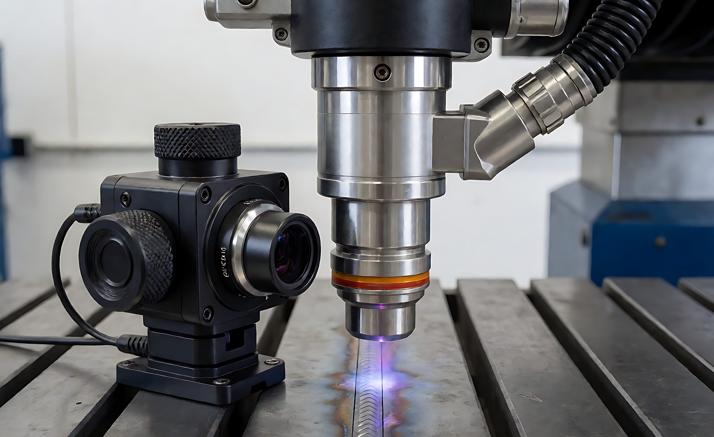
Видение сварочной ячейки и отслеживание шва: что нужно специфицировать
Seam tracking is bought for one reason: to absorb variation. Parts arrive with gaps, edges are not where the drawing said, fit-up drifts through a batch, and thermal distortion moves the joint while it is welded. A programme written to a nominal path welds a nominal part perfectly and a real part inconsistently. A vision system measures where the joint actually is and corrects the path within its own limits. Specifying one is therefore not a question of whether to buy it, but of which variation must be absorbed, to what tolerance, and at what cost in cycle time.
The marketing language is deliberately vague: systems are sold as making the cell self-correcting, which is true within a band and false outside it. The specification should state that band – maximum lateral offset, maximum gap, maximum height change and joint type variation the system must handle while still producing an acceptable weld.
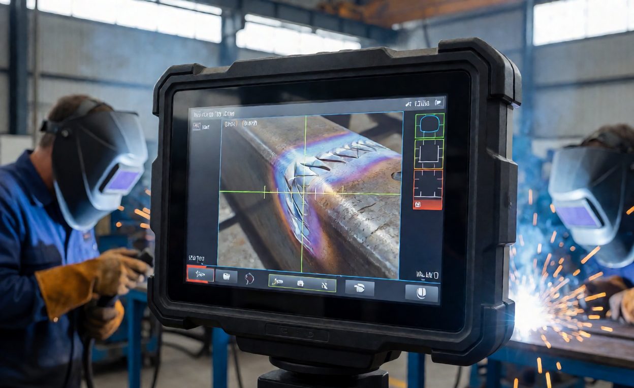
Sensing Principles and What Each Handles
Three sensing approaches cover nearly all laser welding applications, and they are not interchangeable:
- Laser triangulation profile sensing: a laser line is projected across the joint and viewed at an angle. The profile gives joint position, gap width and mismatch in one measurement, and handles gap variation well.
- Structured light area scanning: a pattern is projected wider and reconstructed in three dimensions. Suits complex or curved joints, at higher cost and slower cycle contribution.
- Direct vision with illumination: a camera views the joint under controlled lighting. Cheaper, but sensitive to surface finish, glare and fume.
- Through-the-optics sensing: the sensing path shares the welding optics. Compact near the tool centre point, with a restricted field of view.
- Tactile probing: mechanical or electrical touch sensing before welding. Robust for joint finding, useless for continuous correction.
Two modes then separate what the system does with the measurement: joint finding searches before welding starts and shifts the programme; continuous tracking corrects the path while welding. Most production cells need both, and the specification should say so rather than assume tracking includes searching. Machine vision is the general discipline, and structured light the projection principle behind most profile sensors on welding heads.
Accuracy, Speed and What They Cost
Accuracy figures are quoted under laboratory conditions, and two mechanisms erode them on a real cell:
- Lead distance: the sensor looks ahead of the weld pool by a fixed distance, so correction applies to where the joint was. On a long seam with continuous drift that lag is a systematic error unless the control compensates.
- Время цикла: searching takes time. A scan at each seam start, scans along a long seam and controller dwell all add seconds – and seconds are what the capacity case is built from.
Both are specification items: ask for stated repeatability under production conditions and for added cycle time measured on a real seam. The advanced seam tracking techniques article goes deeper on the control side; the seam tracking automation overview shows where sensor-based correction fits into a cell architecture.
Environmental Requirements Buyers Underestimate
Vision on a welding cell works in a hostile environment, and most field problems traced back to “the sensor is unreliable” turn out to be environment problems:
- Process light: the weld produces intense light across a wide spectrum. Narrowband filtering matched to the sensor laser, plus optical shielding, keeps the image usable.
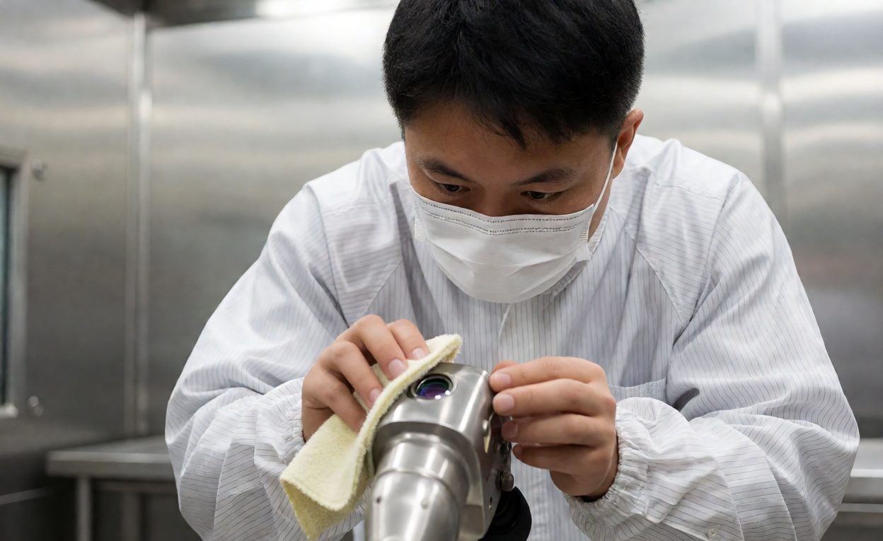
- Fume and spatter: an unprotected sensor window drifts out of calibration within a shift. Air knives, shutters and a cleaning interval belong in the specification, as covered in the обсуждение систем удаления фуг и контроля брызг article.
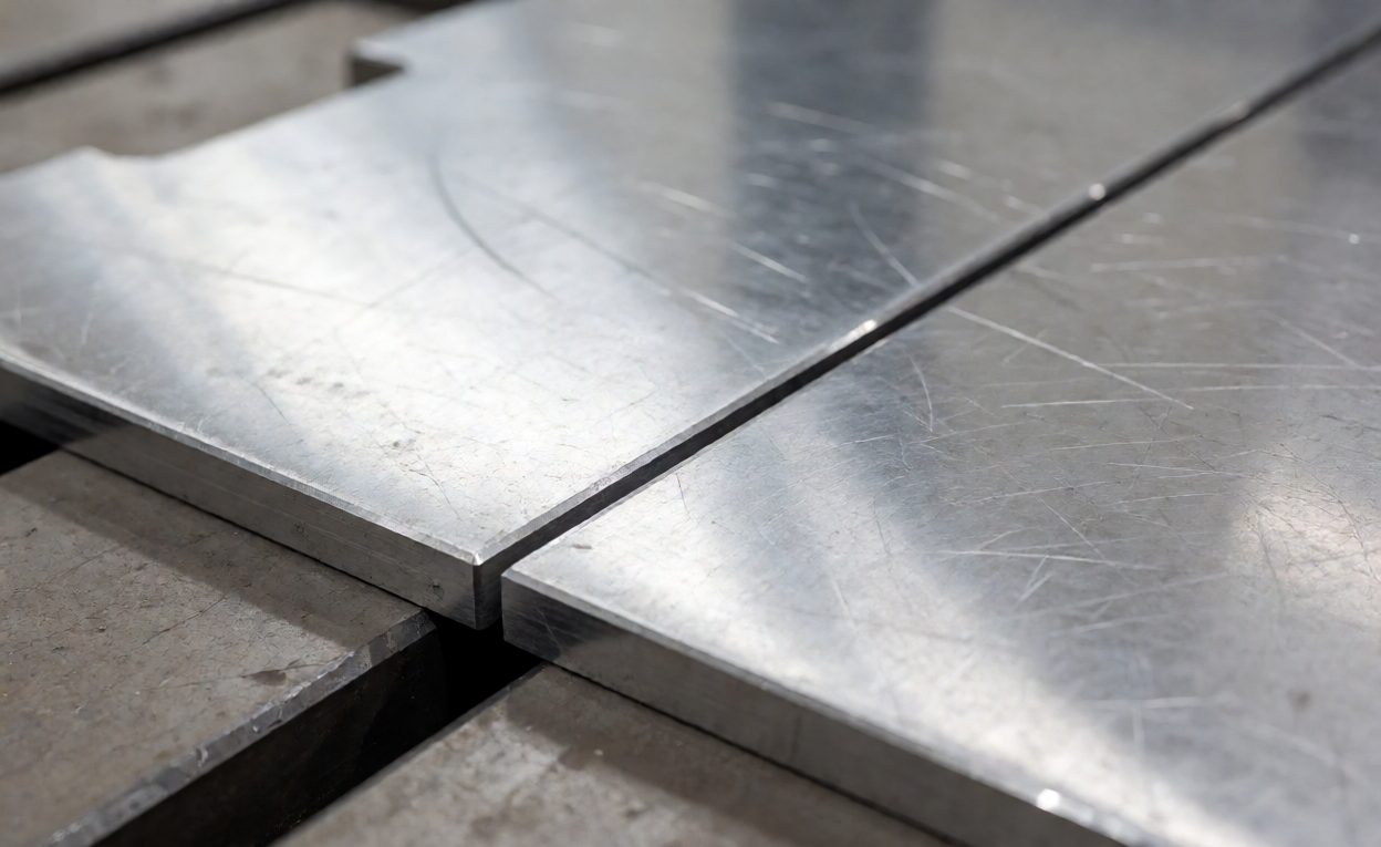
- Surface condition: mill scale, oil, primer and brushed finishes change reflectivity and confuse edge detection, so trials must use production-finished material.
- Cable management: sensor cabling alongside the welding package is a failure point; routing and strain relief belong in the mechanical specification.
Joint design still governs whether tracking is needed at all, since tighter fit-up reduces the correction burden – the руководстве по проектированию стыков и допуску на сборку should be read before the sensor is specified. Better tooling reduces it further, and the fixture design guide explains how repeatable clamping shrinks the variation the sensor must chase. Tracking should absorb what remains after design and tooling have done their work, not compensate for avoidable scatter.
Acceptance Testing the System
Seam tracking is the cell component most often commissioned and least often tested. A short acceptance run settles it:
- Deliberate offset parts: shimmed samples with known offsets at the specification limit, welded and sectioned to confirm penetration held.
- Gap variation set: parts spanning the stated gap range, welded and verified the same way.
- False detection check: the correct behaviour when the joint cannot be found is a controlled stop with a clear alarm, not a weld down a guessed path.
- Drift check: the same part welded at the start and end of a shift, measured to confirm the sensor has not wandered.
Document the results and keep the sample parts. They become the reference set for requalification after any head repair, and the fastest way to distinguish a process problem from a sensor problem later. Recording what was tested also supports the weld acceptance criteria agreed with the supplier, since the criteria and the tracking capability must be consistent. Edge detection is the image processing step at the heart of every profile sensor, and knowing that it depends on contrast predicts most problems that appear when a new material finish enters the cell.
Часто задаваемые вопросы
Does every robotic laser cell need seam tracking?
No. Cells with tight fit-up and repeatable tooling may not need it. High-mix or distortion-prone work usually does.
What is the difference between joint finding and tracking?
Finding locates the seam before welding starts; tracking corrects the path continuously while welding. Most cells need both.
How much cycle time does tracking add?
It depends on scan strategy and seam length. Ask for the measured added seconds per part on a real seam.
Why does accuracy drop on real parts?
Sensor lead distance, surface finish, fume, spatter and thermal drift all erode laboratory accuracy.
How is the sensor window kept clean?
Air knives or shutters plus a defined cleaning interval; without them the sensor drifts within a shift.
What should happen if the sensor loses the joint?
A controlled stop with a clear alarm, never a weld along a guessed path.
Can tracking compensate for poor fit-up?
Within a stated band only. Design and tooling should reduce variation first; tracking absorbs what remains.