
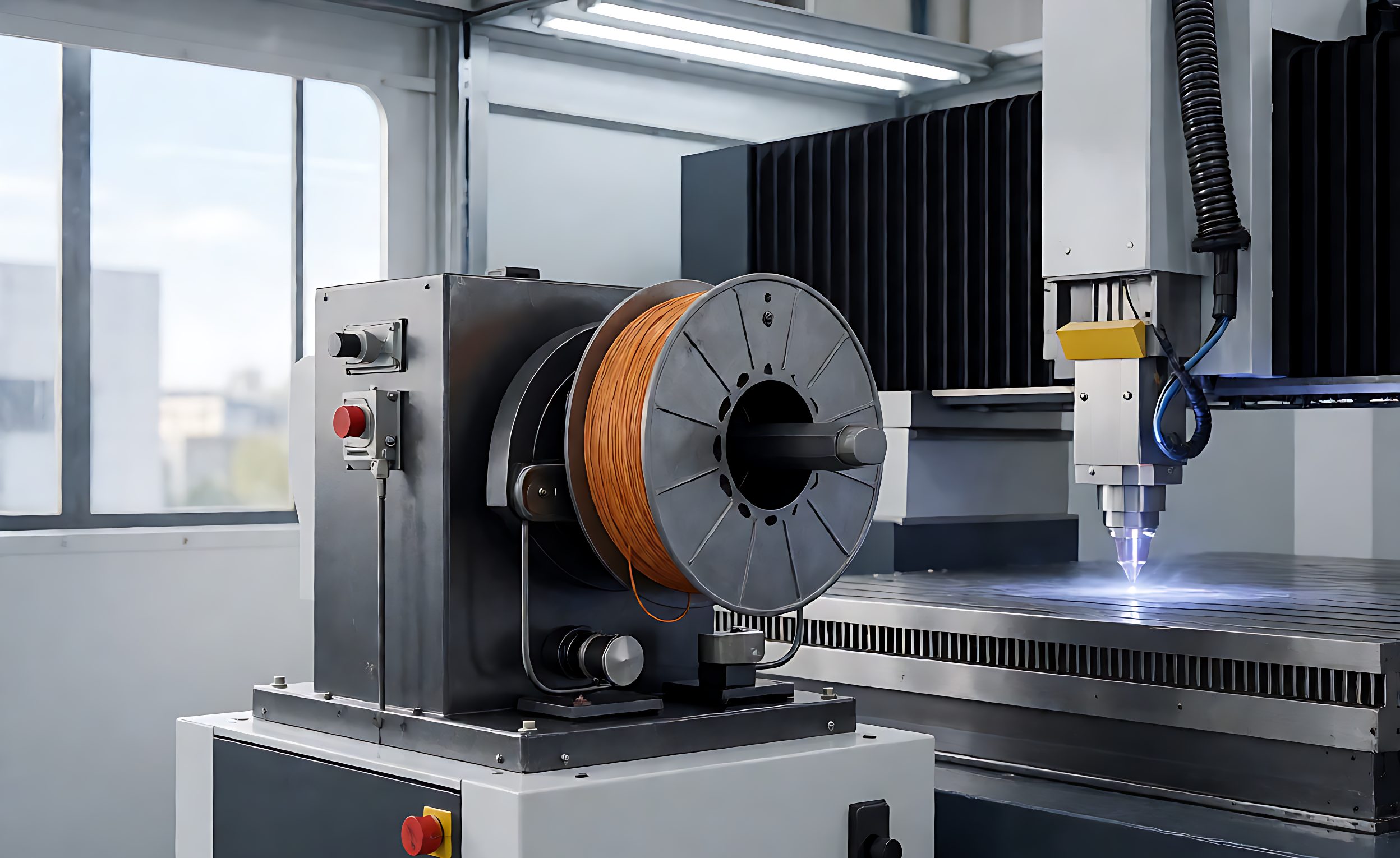
레이저 용접 와이어 피드 시스템 선택: 실용 가이드
Wire feed hardware sits at the bottom of most robotic laser welding quotations and at the top of post-commissioning defect lists. The laser source gets specified by brand and power, the robot by reach and payload, and then the wire feeder appears as a single accessory line with no make and no stated tolerance. In a wire-fed process it decides whether the weld has consistent reinforcement or wanders between undercut and excess buildup.
This guide sets out what to specify, in decision order: which feeder architecture suits the duty, how the wire is driven and guided, and what to check at commissioning. The strategic question of filler versus autogenous welding is covered in the filler strategy comparison; here the process is wire-fed and the question is which system to buy.
Feeder Architecture: Push, Pull and Push-Pull
The choice is driven by wire diameter, material and the distance between feeder and head.
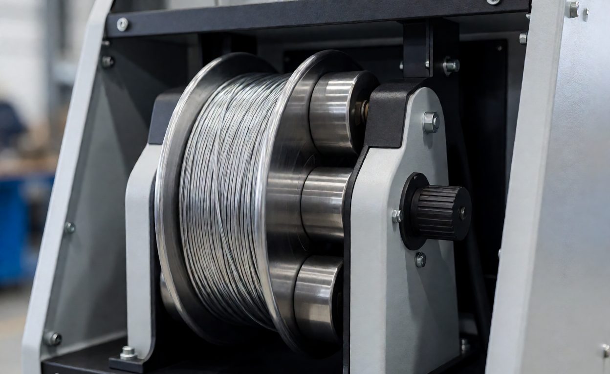
- Push system: the standard arrangement for steel wire in the 0.8 to 1.2 millimetre range over short to moderate conduit runs – simple, cheap, and adequate when the wire is stiff enough not to buckle.
- Push-pull system: a secondary motor at the head shares the driving. Required for aluminium and other soft wires, and for long conduit runs, because soft wire buckles in the liner long before the feeder shows a fault.
- Spool-on-head: a small spool carried on the wrist, removing the conduit entirely at the cost of wrist payload, spool change frequency and protection in a harsh environment.
Aluminium deserves its own warning. The aluminium parameter window article covers the metallurgical side; on the equipment side, aluminium wire feeds reliably only with a push-pull system, a U-groove or polished V-groove roll, and the shortest practical conduit. Specifying a push feeder for aluminium is the most common wire feed mis-selection; it shows up as erratic feed that looks like a parameter problem.
Drive Rolls, Liner and Guidance
Between spool and contact point, four components decide feed consistency, each with a specification worth writing down.
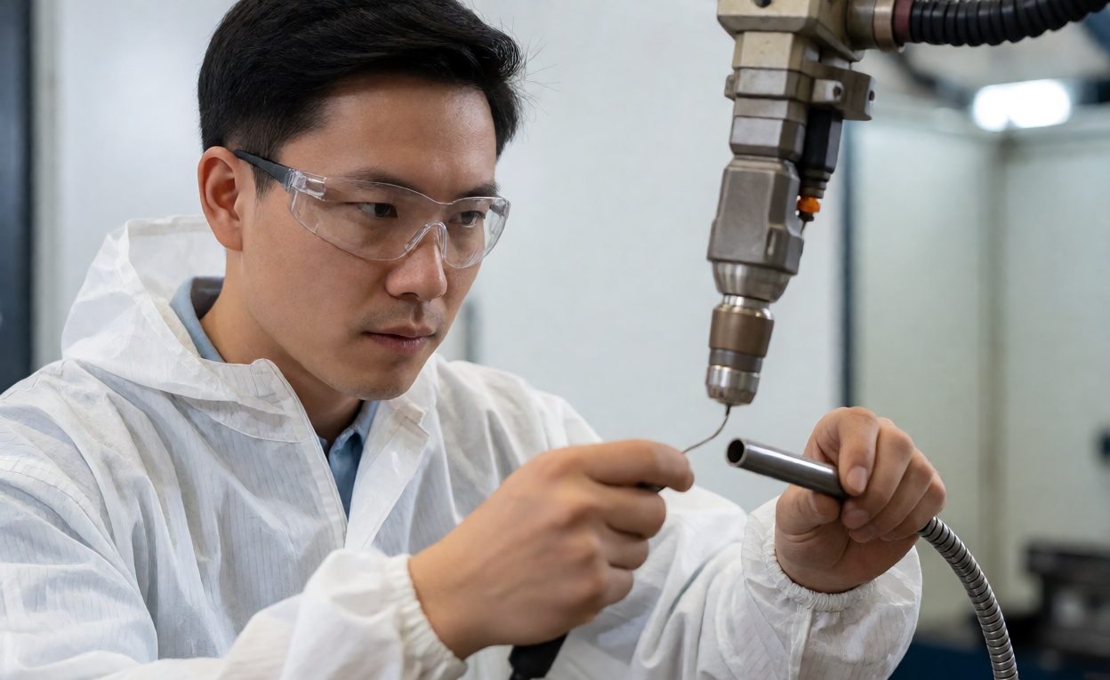
- Drive rolls: matched to wire diameter within a tenth of a millimetre, grooved to suit the wire type, and pressure set to drive without slipping or deformation. Marked roll sets per diameter avoid running 1.0 millimetre wire on 1.2 rolls.
- Liner: correct length – excess liner adds friction, the enemy of stable feeding. Spiral steel for steel; PTFE or carbon for aluminium.
- Guidance path: the conduit route should avoid tight bends, and the robot programme should not introduce new ones. A dress pack looping the conduit tighter than its rating produces feed variation that moves with the torch pose.
- Feed speed interface: wire feed speed must be programmable and integrated with the weld schedule, not set by a front-panel knob, or the cell cannot run mixed work properly.
Feed consistency is measurable at acceptance: run a timed feed into a bin at three programmed speeds and weigh the wire delivered. Deviation beyond a couple of percent across poses indicates a routing or pressure problem, cheap to fix now and expensive to diagnose later.
Wire Itself: Selection, Condition and Storage
그만큼 consumables cost breakdown treats wire as a running cost; here it is a system component. Wire chemistry must match the joint design, and the surface condition matters more than most buyers expect. Drawing lubricant residue and surface oxides cause porosity, so vacuum-sealed spools and clean storage are worth specifying.
Spool size is a genuine decision. Large spools reduce changeovers, but wire left exposed on a half-used spool picks up contamination, and every restart begins with suspect wire. A written rule – cut back a defined length after any idle period – costs nothing and removes a real porosity source.
Head Integration and Shielding
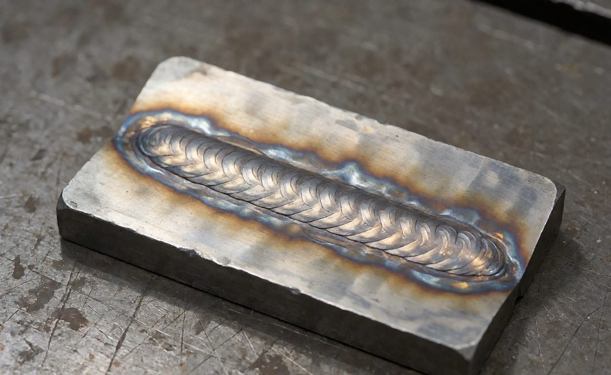
Where the wire meets the weld matters as much as how it got there. The delivery point needs three things defined: contact or guide tip position relative to the focal point, wire stick-out control as the torch moves, and shielding gas arrangement at the wire entry. Gas coverage for a wire-fed laser weld differs from the autogenous case, and undersized coverage produces a porosity signature that parameter tuning will never fix.
Integration with the head also includes crash protection and tip access. A contact tip that requires dismounting the head to change will be skipped, and a skipped tip change becomes a mid-shift feed fault. Specify hand-changeable tips, and put them on the 첫해 예비 부품 키트 list with the drive rolls and liners.
Commissioning Checks Worth Writing Into the Acceptance Test
- Feed accuracy: timed feed weight test at three speeds and torch poses.
- Run-in behaviour: weld start repeatability over at least fifty starts; wire ramp-in is where most start porosity lives.
- Seam tracking interaction: if tracking is fitted, confirm the tracker’s reference point accounts for the wire tip, per the seam tracking article.
- Quality verification: section the first production-representative coupons rather than judging surface appearance, using the methods in the weld quality verification guide.
Wire feed systems are not exotic technology – filler metal delivery has been engineered for decades, and the mechanisms in GMAW equipment established the drive and liner principles every modern feeder follows. What is specific to laser welding is tolerance: the pool is small and fast, with little time to forgive a feed hiccup. Welding wire specification, drive setup and routing are therefore process inputs on the level of power and travel speed, and buyers who specify them explicitly at quotation stage commission in days instead of weeks.
자주 묻는 질문
When does a push-pull feeder become necessary?
For soft wires such as aluminium, fine diameters, and conduit runs long enough that pushed wire buckles.
Does spool size matter?
Yes, but large spools expose wire to contamination longer. Balance changeover labour against storage discipline.
Why does wire feed speed need robot integration?
Mixed production needs different feed speeds per part and weld. A front-panel knob cannot be scheduled, recorded or repeated.
What causes erratic feeding that looks like a weld defect?
Mostly liner length, tight conduit bends in the dress pack, wrong roll grooves or pressure. Feed weight testing separates feed faults from parameter faults.
Should wire be discarded after idle periods?
Discard the exposed length after any significant idle period; contamination on stale wire is a common, preventable porosity source.
How is feed accuracy verified at acceptance?
Time a feed into a container at three speeds and poses, weighing the delivered wire; deviation beyond a few percent indicates a routing or pressure problem.
Which spares should be stocked for the feeder?
Drive rolls per size, liners, contact tips, and a spare drive motor for high-duty cells.