Automatización del Plegado de Metales: Una Guía Paso a Paso para la Integración de Robótica en Prensas de Doblar
Las operaciones manuales de la prensa de doblar presentan desafíos significativos en la fabricación moderna de chapa metálica. El manejo de placas grandes, pesadas o afiladas expone a los operadores a peligros de seguridad, mientras que los ciclos de doblado repetitivos contribuyen a la fatiga física y a ángulos inconsistentes.
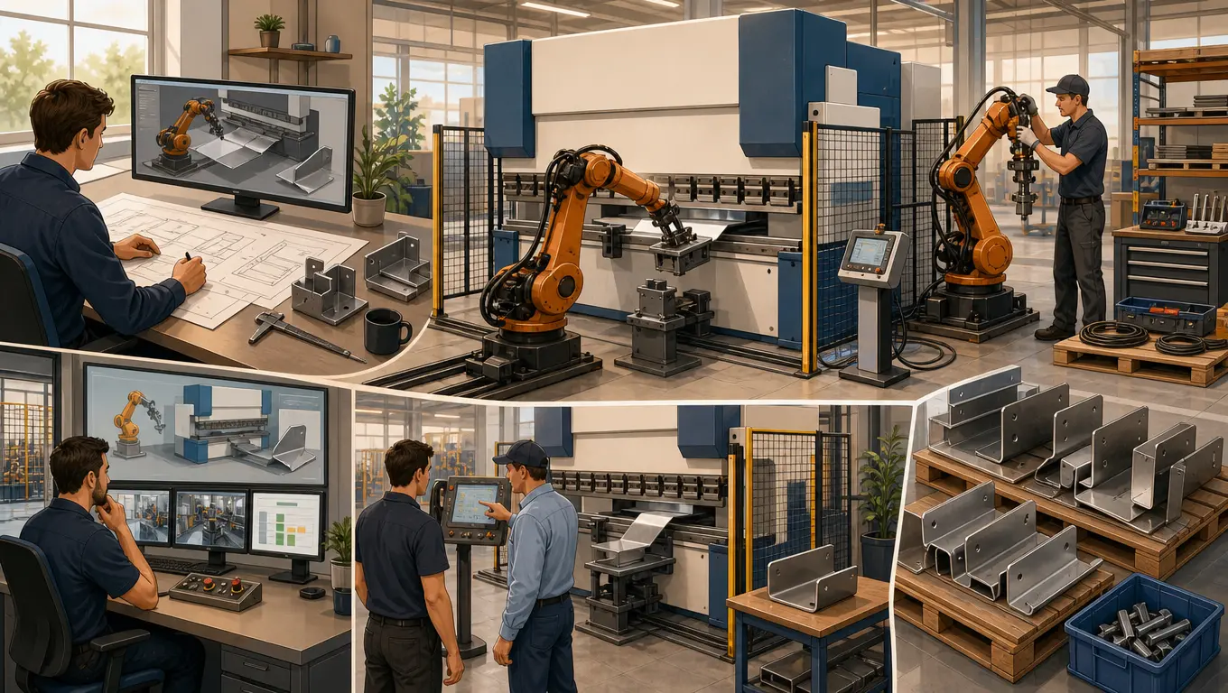
Automatizar estas operaciones con un máquina de plegado robótica especializado ayuda a abordar estos desafíos. Al integrar un robot articulado multieje con una prensa de doblar sincronizada, los fabricantes pueden ejecutar una producción continua y consistente. Esta guía proporciona un tutorial paso a paso sobre cómo configurar, programar y optimizar una celda de doblado de prensa industrial.
Preparación y requisitos previos del sistema
Antes de programar tu celda robótica, verifica que tu hardware y las interfaces mecánicas cumplan con los estándares necesarios para la automatización. Las prensas de doblar diseñadas para operación manual a menudo carecen de los protocolos de comunicación digital requeridos para la sincronización en tiempo real.
Lista de verificación de hardware esencial
- Prensa de doblar con interfaz de automatización CNC: El controlador de la prensa de doblar debe admitir el intercambio de señales digitales (como EtherCAT, Profinet o enlaces de E/S dedicados) para coordinar los movimientos del backgauge con las trayectorias del robot.
- Robot articulado para doblado: Un robot de 6 ejes con una carga útil que coincida con la pieza más pesada y el conjunto de pinzas. Para piezas de trabajo extendidas, un robot montado en un sistema de riel de piso robótico expande significativamente el envolvente de operación.
- Conjunto de pinzas de doble acción: Una pinza que combina ventosas neumáticas (para grandes áreas superficiales) y abrazaderas mecánicas (para aletas estrechas o bloqueo mecánico seguro).
- Estación de separación de chapas: Equipada con ventiladores magnéticos (para metales ferrosos) y cuchillas de aire para evitar que el robot tome varias chapas simultáneamente.
- Mesa de alineación/centrado por gravedad: Un accesorio físico utilizado para alinear los bordes de la chapa, corrigiendo cualquier error posicional menor introducido durante la fase de recogida.
Guía paso a paso para la integración del doblado
Una secuencia de doblado automatizado confiable depende de coordenadas precisas y repetibles y de un movimiento coordinado. Sigue estos pasos para configurar el flujo de trabajo de tu celda:
Paso 1: Carga de chapa y detección de doble chapa
El robot se mueve hacia la paleta de material en bruto. Antes de levantar, los ventiladores magnéticos aplican un campo magnético localizado para separar las chapas de acero apiladas. La pinza toma una pieza en blanco y la pasa sobre un sensor de espesor de doble chapa (contacto mecánico o ultrasónico). Si el sensor detecta una variación de espesor (por ejemplo, midiendo 3,0 mm en lugar de los 1,5 mm especificados), el ciclo se detiene y la chapa se rechaza para evitar dañar la herramienta de la prensa de doblar.
Paso 2: Centrado preciso en la mesa de gravedad
Incluso con las piezas en blanco alineadas, los palés de chapa en bruto pueden desplazarse durante el transporte. Para establecer una referencia de coordenadas precisa, el robot coloca la pieza en blanco sobre una mesa de centrado inclinada. La gravedad desliza la pieza contra topes de referencia mecánicos de punto cero. Una vez alineada, el robot bloquea su pinza nuevamente sobre la chapa, guardando el nuevo desplazamiento de coordenadas en su registro.
Paso 3: Sincronización de la trayectoria de herramientas con la trasera de la plegadora
El robot maniobra la chapa hacia la garganta abierta de la plegadora, presionando el borde posterior contra los dedos de la trasera CNC. En esta etapa, ocurre un intercambio de señales digital:
- El robot envía una señal de “Pieza en posición” a la plegadora.
- La plegadora sujeta ligeramente la chapa con el troquel superior.
- La trasera se retrae para despejar la trayectoria de la próxima dobladura, y la plegadora envía una señal de “Seguro para doblar” de vuelta al robot.
Paso 4: Seguimiento dinámico de trayectorias en arco
A medida que el punzón de la plegadora presiona el metal en el troquel en V, la chapa plana pivota hacia arriba. El robot debe seguir dinámicamente este arco de rotación. Si el robot se mueve demasiado lento, la chapa puede doblarse por su propio peso o deslizarse de la pinza. Si el robot se mueve demasiado rápido, puede arrancar la chapa del troquel, causando riesgos de seguridad o daños en la pieza.
Los modernos robots de doblado de plegadoras utilizan un “paquete de software de doblado” dedicado. Este software calcula el centro de rotación (que se desplaza a medida que el material se deforma) y sincroniza la velocidad ascendente del brazo del robot con la velocidad del émbolo de la plegadora, manteniendo una alineación constante durante todo el recorrido.
Paso 5: Reagarrado y paletizado final
Para piezas con múltiples dobladuras en lados opuestos, el agarre físico del robot puede eventualmente bloquear la trayectoria de las herramientas. El robot puede colocar la pieza parcialmente formada en una estación intermedia de reagarrado, liberar su agarre, reposicionar la pinza en una aleta sin doblar y recuperar la pieza para completar las dobladuras restantes. Una vez terminado, el robot coloca la pieza en la pila de salida en un patrón de anidamiento predefinido.
Solución de problemas de cuellos de botella comunes en automatización
Las celdas de doblado industriales operan dentro de márgenes mecánicos ajustados. Las pequeñas variaciones del material pueden afectar la calidad general de la pieza. A continuación se presentan problemas comunes y pasos correctivos recomendados:
| Problema observado | Causa raíz probable | Acción correctiva recomendada |
|---|---|---|
| Desviación angular entre diferentes lotes | Variaciones en la dureza del material o tolerancias del espesor de la chapa (que causan variaciones en el resorte). | Integre un sensor de medición de ángulo láser en tiempo real (como LAMS) en la plegadora para ajustar la profundidad de plegado sobre la marcha. |
| Deslizamiento de la pieza desde las pinzas de succión | Superficies de láminas aceitosas, escamas de laminación o altas tasas de aceleración durante las transiciones del robot. | Aumente los límites de umbral de vacío, integre abrazaderas mecánicas de borde y reduzca los ajustes de sacudida en el programa de transición. |
| Rayones en la superficie de la pieza terminada | Contacto metal con metal con la matriz o las ventosas que atrapan partículas abrasivas. | Instale cubiertas protectoras de matriz de nylon (cinta protectora en V) y use ventosas de poliuretano que no marquen. |
| Alarmas de colisión del retroceso | Señalización desincronizada entre la plegadora y el controlador del robot. | Revise la secuencia de enlace; asegúrese de agregar un paso de retardo para que el retroceso se retraiga completamente antes de que comience el golpe de plegado. |
Selección y configuración de la pinza
La pinza es un componente crítico de una celda de plegado automatizado exitosa. Las pinzas diseñadas a medida permiten que un solo robot maneje una amplia gama de formas y tamaños de piezas.
- Sistemas de cuadrícula de vacío: Excelentes para paneles grandes y planos. Al agrupar las ventosas en zonas neumáticas independientes, puede activar selectivamente las zonas según la geometría de la pieza.
- Mandíbulas de sujeción neumáticas: Esenciales para piezas pesadas, perfiles estrechos o piezas con grandes recortes donde las ventosas no pueden lograr un sellado. Las mandíbulas de sujeción proporcionan un bloqueo mecánico positivo, lo que permite transiciones rápidas sin riesgo de deslizamiento.
- Cambiadores automáticos de pinzas (ATC): Para talleres de alta mezcla y bajo volumen, un ATC permite que el robot cambie entre matrices de vacío y garras mecánicas en menos de 10 segundos, manteniendo la producción continua en trabajos variados.
Preguntas frecuentes
P: ¿Puede una máquina de plegado robótico manejar pequeños lotes de producción, o solo es para trabajos de alto volumen?
R: Aunque históricamente se reservaba para producción de alto volumen, el software moderno de programación fuera de línea (OLP) permite a los operadores importar archivos CAD 3D y generar automáticamente trayectorias de robot sin colisiones en minutos. Esto hace que las celdas automatizadas sean rentables para lotes de tan solo 20 a 50 piezas.
P: ¿Cómo compensa la automatización del plegado de metales la recuperación elástica del material?
R: La compensación se maneja ya sea preprogramando la recuperación elástica esperada basada en plegados de prueba, o utilizando sistemas activos de medición de ángulo en la plegadora. Estos sensores miden el ángulo de recuperación elástica en tiempo real mientras la herramienta se abre, y realizan automáticamente un breve golpe secundario para alcanzar el ángulo objetivo.
P: ¿Qué normas de seguridad se aplican a las celdas de plegado robótico industrial?
R: Las celdas de plegado automatizado deben cumplir con las normas internacionales de seguridad, incluidas ISO 10218-1/2 para robots industriales y ANSI B11.3 para plegadoras. Las medidas de seguridad generalmente incluyen vallas de seguridad, cortinas de luz y escáneres de seguridad para proteger a los operadores de láminas en movimiento rápido y puntos de pellizco.
Conclusión y configuración personalizada
Automatizar las operaciones de su prensa de doblar con una celda de doblado robótica ayuda a mejorar la seguridad, reducir los costos de mano de obra y ofrecer una calidad de pieza constante. Aunque la configuración física requiere un diseño cuidadoso, las ganancias a largo plazo en tiempo de actividad y repetibilidad ofrecen un retorno de inversión confiable.
TrueSyn ofrece servicios completos de integración, desde el diseño de pinzas personalizadas hasta la programación sincronizada para su prensa de doblar. Póngase en contacto con nuestro equipo de aplicaciones para realizar simulaciones con sus piezas y explorar una solución de automatización adaptada.
Obtenga orientación experta sobre su automatización de doblado
Discuta los diseños de sus piezas y los objetivos de tiempo de ciclo con nuestro equipo:
- Correo electrónico: wangd@zjcxlaser.com
- WhatsApp (Sr. Peng): +86-13615855016
- WhatsApp (Sra. Wang): +86-13185595609
- Vea nuestros sistemas en acción en YouTube: Canal de Automatización Robótica de TrueSyn