
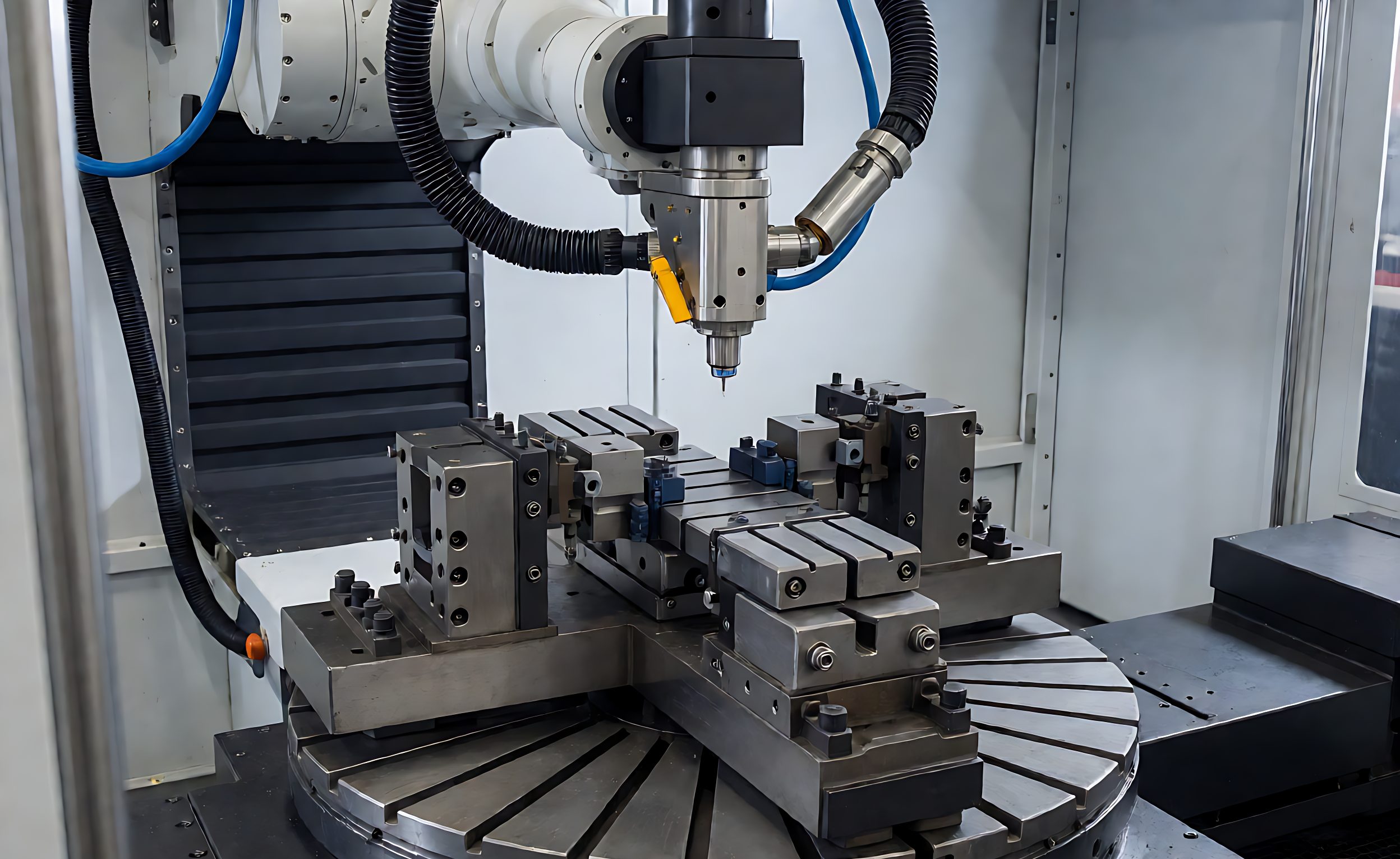
Diseño de sujeción para soldadura en células de láser robotizadas: Sujeción, acceso y repetibilidad
In robotic laser welding, the fixture is half the process. The robot repeats whatever path you teach it with impressive precision — but it repeats it relative to the part position the fixture guarantees. A fixture that loads inconsistently, blocks the beam at the wrong angle, or transmits heat into the wrong place will produce scrap at robot speed. This guide covers the design decisions that decide whether a fixture works: clamping strategy, laser access, datum logic and the joint design handoff between mechanical fixture and robot program.
Budget context first: fixtures are a real line item in the workcell and tooling cost breakdown, often second only to the robot itself for complex parts. Designing them well once is cheaper than designing them twice.
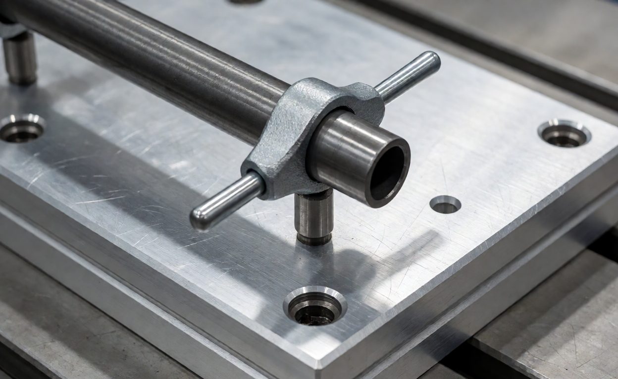
Clamping: Hold the Part Where the Beam Can Still Reach
The central tension in laser fixture design is that clamps occupy space, and the laser needs clear line of sight to the joint from its working angle. A clamp head sitting 15 mm from the seam can shadow the beam or reflect it. Practical rules:
- Clamp away from the joint line, on the far side of the part or below the seam, so the beam approaches at its intended angle without striking steel hardware.
- Prefer low-profile clamps and locators. Swing clamps that retract clear of the cell’s working envelope let the robot reach every seam without a re-clamp cycle.
- Clamp force: enough to seat, not to distort. Laser welds are low heat input, so the classic heavy clamp forces of arc welding are usually unnecessary and risk distorting thin gauge. Over-clamping a 1.5 mm sheet telegraphs into the weld.
- Plan for tacking: if the process tacks then welds, the fixture must hold accuracy with fewer active clamps in the second step. Design the locator layout so the part stays fully constrained between tacks.
Datums and Repeatability: Design Like a Machinist
Borrow the logic of machining fixtures: constrain the part once with a 3-2-1 scheme, and never ask the operator to “eyeball” position. Every locator should reference a feature that exists on every part — a machined edge, a punched hole, a formed flange — not a raw saw-cut that varies batch to batch. If the upstream part varies, the fixture must absorb that variation in a controlled direction, or the weld will trace it.
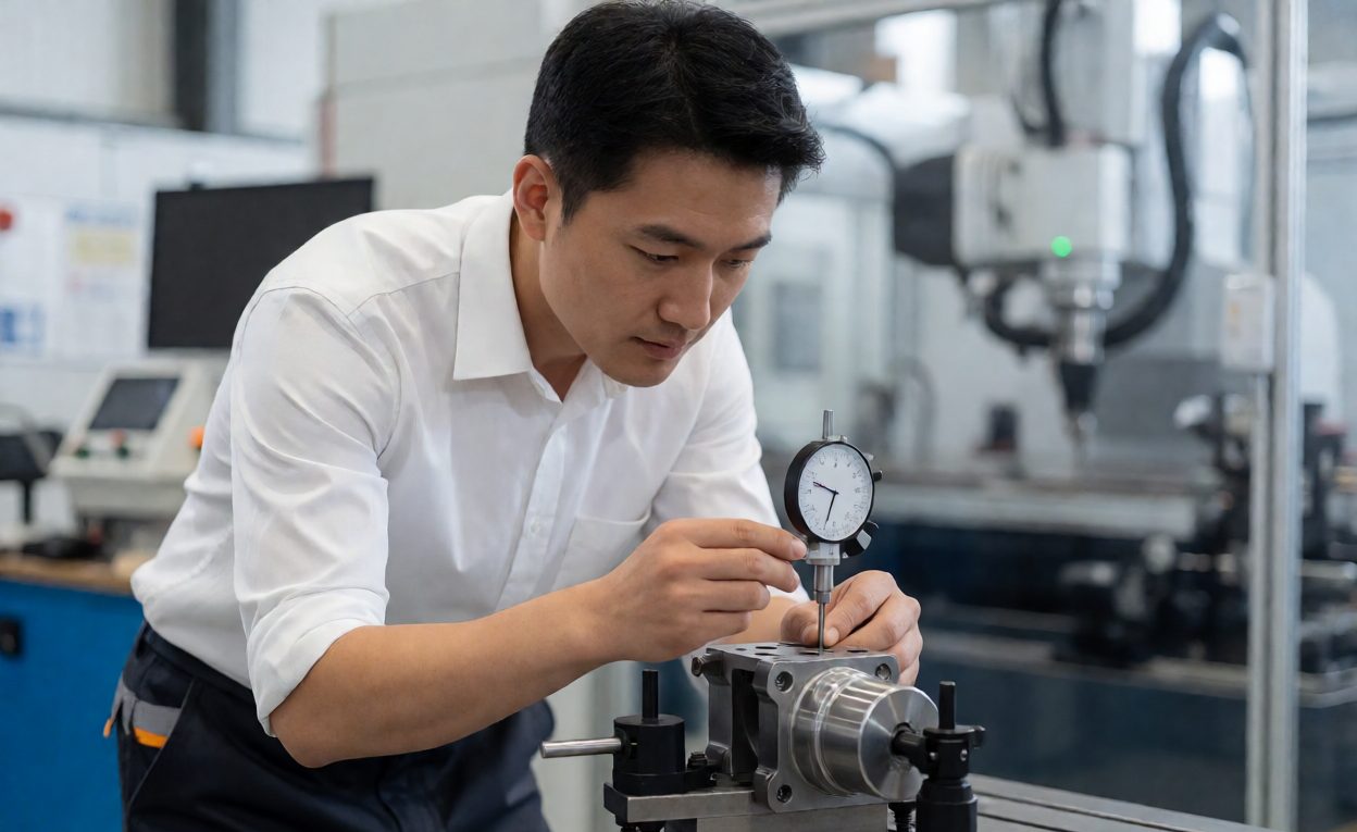
Repeatability is measurable. Load and unload a part ten times and indicate the same reference point each cycle; the spread is what your robot program will inherit. Weld quality procedures such as macro-etch and penetrant checks will eventually expose a wandering seam as a fixture problem, but a dial indicator finds it in an afternoon.
Technical background: the discipline behind this is formalized in jig and fixture practice, where datum references define how a part is located in degrees of freedom, and clamping applies force without disturbing the location. Laser welding inherits all of it, plus one optical constraint arc welding never had: nothing may block the beam path.
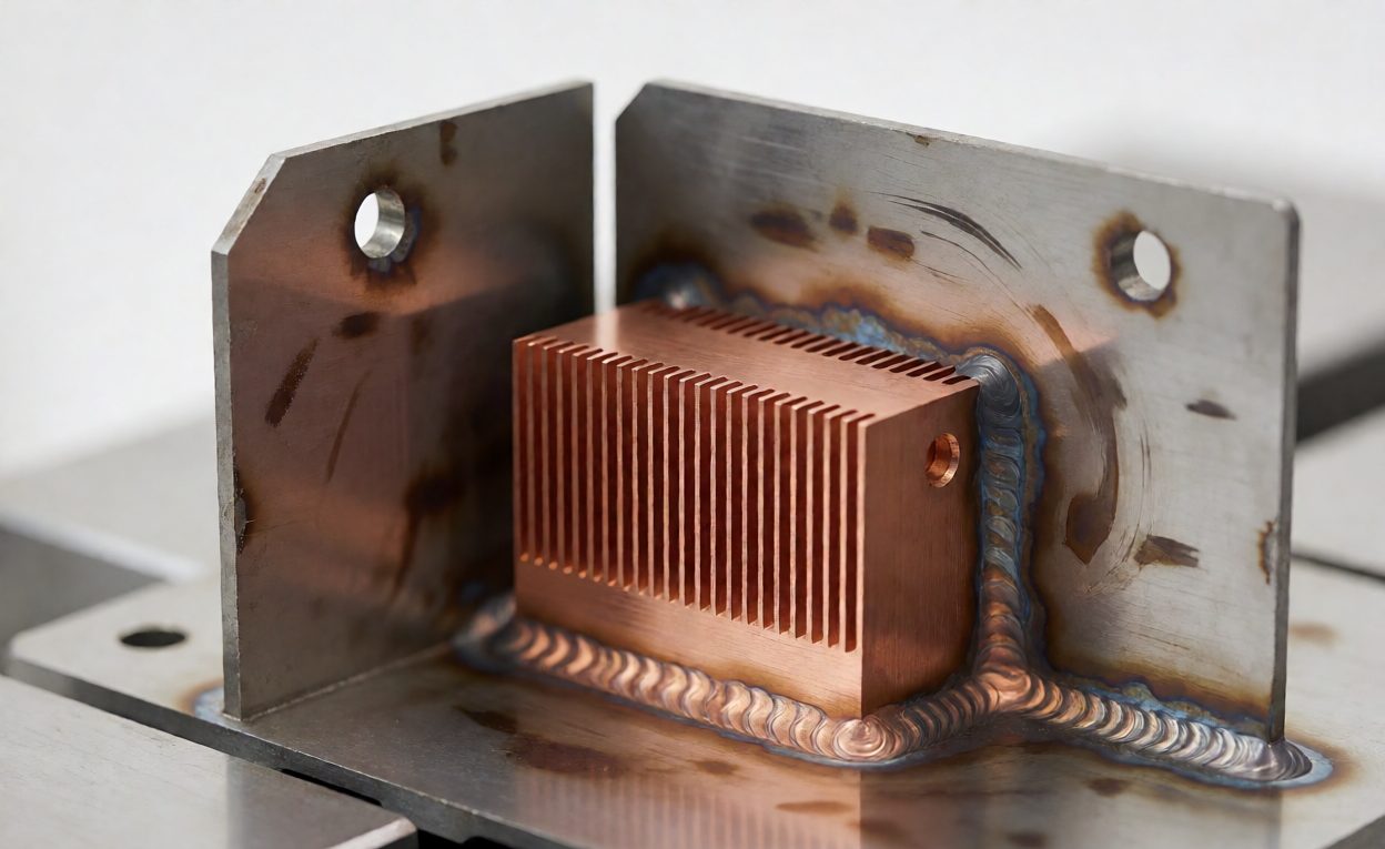
Heat Management: Copper, Backing and Gap Control
Laser welding concentrates heat tightly, but thin parts still warp and joint gaps still bite. Fixtures participate in heat control directly:
- Copper backing bars and inserts under or beside the seam sink heat and support the root. They also protect fixture steel from weld spatter and accidental beam strikes — copper shrugs off what steel would crater on.
- Gap control features — locating pins that double as gap setters — keep the joint gap in the range your laser power and focal position were chosen for. A gap that grows along a seam shows up as a weld that starts strong and tunnels.
- Spatter shields on everything near the joint. Nozzle contamination is routine; fixture contamination compounds every cycle until parts stop seating.
Design the Fixture and the Program Together
The worst handoff in automation is a fixture delivered to the integrator as a done deal, with the robot program written around whatever access is left. Involve the programmer during fixture design: reachability for every seam, the weld sequence relative to clamps, part load orientation for the operator, and where the seam-tracking sensor looks. For turnkey lines, this is exactly what a competent integrator forces early; for component purchases, you must force it yourself.
Two more practical notes. First, safety review is part of fixture design: opening the fixture should interrupt the cell, and light-tight interlocks matter as described in the Class 4 laser safety framework — a fixture with a gap in guarding is a beam escape path. Second, plan the fixture’s own maintenance: spatter cleaning, locator wear checks and clamp service keep repeatability from drifting month over month.
¿Qué tan cerca puede estar un prensajador de la costura de soldadura láser?
Far enough that the beam at its working angle never strikes the clamp, which usually means at least 10–15 mm clear of the seam path plus reflective safety margin. The exact distance depends on the head angle and focal length, so finalize it with the programmer during fixture design, not on the shop floor.
Do laser welding fixtures need less clamping force than MIG or TIG fixtures?
Generally yes. Laser welding has low heat input and distortion, so seating force matters more than brute clamping. Over-clamping thin sheet distorts the part and telegraphs into the weld. Clamp to seat against locators, not to deform.
What is the 3-2-1 locating principle in fixture design?
Three points set the primary plane, two set the second axis, one sets the third — six contact points fully constrain a rigid part. Design locators against features that exist on every part, and the part loads the same way every cycle, which is what the robot program assumes.
How do I verify a fixture is repeatable before production?
Load and unload a part ten times and indicate the same reference surface each cycle. The spread you measure is what the robot inherits. If it exceeds your weld tolerance budget, fix locators or loading method before teaching paths.
Why use copper in a steel fixture?
Copper draws heat away from the joint and survives spatter and stray beam strikes without cratering. Copper backing bars support the weld root and protect the fixture body, extending the fixture’s own life.
Should the robot program be written before or after the fixture is built?
Designed together, programmed in parallel. Reachability, weld sequence relative to clamps, sensor viewing angles and operator load ergonomics all depend on the fixture. Delivering a finished fixture to the integrator and then programming around it is the most expensive possible sequence.
What fixture maintenance keeps welds consistent over months?
Daily spatter cleaning near the joint, periodic locator wear checks with a go/no-go gauge, clamp service, and a quarterly repeatability re-check with the dial indicator. Fixture drift is slow and silent; a scheduled check makes it visible.